Guffy you are brilliant! Thank you for the help. Your initial post suggesting I use pin 9 will most likely work. I made a mistake when I looked up pin 9 on my board pin diagram pictured previously. I thought that was the heater and I said that in my replies. Since pin 9 is the fan that means I don’t have to make any firmware changes. I just use M106/M107 like you said.
I checked last night and my board does indeed use mosfet to ground so I can use the ground pin from the fan and a +5 from somewhere else. Probably XS3 like Bill suggested. I tested with a volt meter from the source +12 to the fan - and it was 0 potential. I set the fan speed to 100% (M106) and it showed 12v. Conversely when I tested the source - to the fan +12 it was always +12v regardless of fan speed settings.
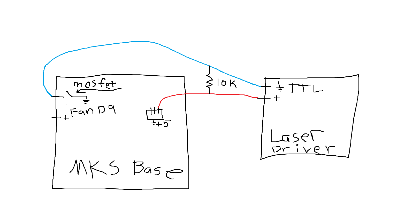
Last night I looked up how a pullup resistor works. In detail it seems complicated but I can simplify it very easily in the picture. Please correct me if I am wrong. I want the TTL to have a constant plus 5V on the + pin. I want the Negative pin on the TTL to also be +5 V (Through the pullup resistor) until I want the laser to be on. That way it will have 0 V potential between the two TTL pins. Then when I send M106 pin 9 on my board will go from open to ground. That will cause a 5v potential across the TTL pins. Some power will go straight through the pullup resistor from +5 to ground but not enough to cause a short. (I will start with a 10K resistor.) Here is a picture of what I will wire up tonight.
[attachment file=“TTL Wireing.png”]
This way I get my 5V pwm and avoid the voltage dividers Ryan said were unusable.
Guffy that link that you provided was incredible. http://marlinfw.org/docs/configuration/laser_spindle.html It helped to show all the pwm enabled pins which is what I really needed to confirm the fan pin would work.
Thank you for the suggestions Bill. Since none of those pins are pwm enabled according the list in the link I don’t think they would work but I really have to wonder if the analog pins A11 and A12 could still somehow be used with the laser driver I have. Because I can flip a switch and have it go from TTL to analog. In any case I have no clue how to do that and I now have enough of an understanding that I think TTL is the way to go.
Thank you. I am 100% sure my board in the older version 1.2 from the previous picture. Old board but still usable. So I am convinced I can use the fan pin 9. I may try to play with the firmware later to see if I can use one of the heater pin sets to power another 12 V fan using the M106 P1. But not tonight.
[attachment file=80021]
So I will be trying to wire this up tonight and get it running. If I let the magic smoke out I will inform everyone that I am once again wrong in my understanding of how things should work. Thank you everyone for the help. I am truly grateful. Cross your fingers because I am gonna try to burn stuff.