The docs are written in markup, which is just like writing these posts.
The second link in my first post above is the one that takes my connection to the exploded view.
Here it is again along with a screen shot of what i’m calling the ‘exploded view’…
\https://www.v1engineering.com/wp-content/uploads/2018/08/Z-assm.jpg
Not sure if you are getting the same view (two pictures of the fully assembled Z, one large, one small) when looking at the web page. I’ll trying using Firefox and Exploder and see if the page isn’t presenting itself the same to both of us.
Thx.
EG
Yeah, I have the links to the images, I’m trying to get a link to the page with the instructions.
Doh!!! sorry.
It looks like Chrome and IE are resolving the page links slightly differently.
Definitely might be something in my Chrome/IE instances, but I’ve seen other posts of people saying they couldn’t see the exploded view of the Z: assembly.
Whoa, that is weird, the thumbnail changed. Hopefully we will be fully moved to DOC’s before too long here. Let me see if I can fix that in the mean time.
My build thread got hijacked lol
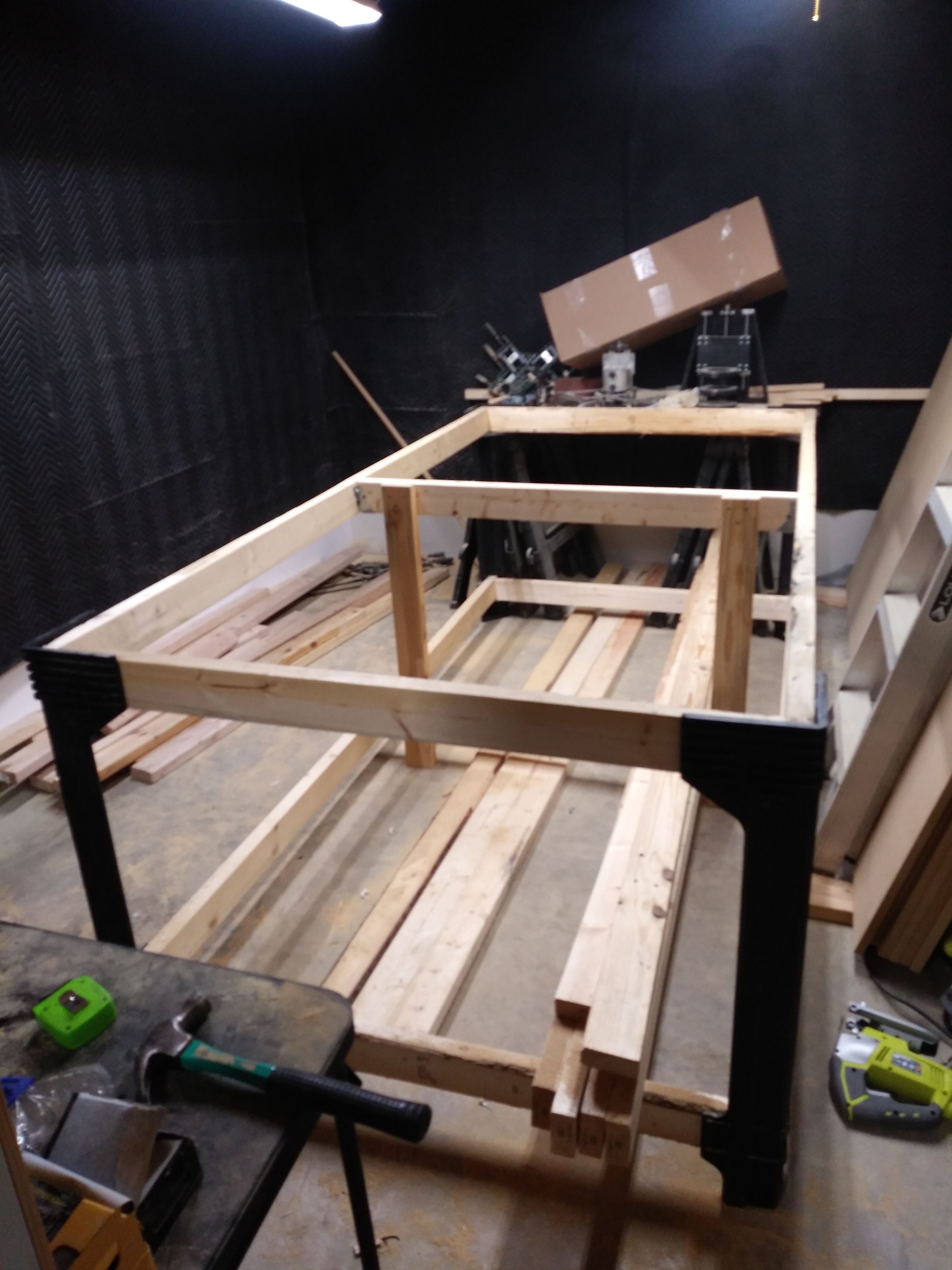
So I know it’s been a while, I had a pretty rough first of the year, and I’m JUST NOW getting back on my LR2 build. I got the frame done today, I’m 1 step closer to being in the full sheet family!
Things that were bothering me… I kept hearing ‘Has to be square’ ‘has to be level’ so I’m nervous af about those 2 things. To the point I was trying to find a table that would work. Then I found some resin legs on amazon. Keeps things square, and level. IF your cuts are good. I totally bought them, and the listing was accurate. My table is square, and level. I DID add some support to the middle section to eliminate any sagging under weight. I used some joist hangers, then shot in some 3" deck screws. I’m really shocked at how sturdy the table is, being the legs are resin. But, color me impressed.
Overlook the mess. I had to take that damn Maslow apart and all those 2x’s are just thrown against the wall. Wish I had a burn permit, I woulda got so much more satisfaction watching it go up in flames. But, I’m not bitter… Just wish I had found the LR2 first.
ANYWAY, so tomorrow I’ll put the top on. I’m building a ‘sorta torsion box’, then Monday, I have the day off, and I’ll put my machine together FINALLY!!! I’m freakin’ excited man… Can’t wait to get it together!
2 Likes
As square as possible is the most important, but don’t worry to much I have never put much effort into flat…if it is bad you will have a robot that can fix it.
Even square can be tweaked with a little sandpaper if needed. But really if it rolls straight it will do so on a parallelogram as long as you start at square.
1 Like
Thanks @vicious1 for the encouraging tips! I put a piece of MDF on it, which I will have as my spoil board. It’s perfectly square with the 2x Frame. No overhang in any places, and flush all the way around. That really made my day, and got the excitement level back up to where it was!
I’m sure I’ll be bugging you guys about the endstops. I’m 100% certain I can get the machine running as I have alot of experience with 3D Printer builds, but those endstops, I’m a lil’ worried about to be honest.
I don’t use them. I mounted the belt/hardstops the best I could then shimmed one with a few layers of tape…square start every time. No need to overcomplicate things. Later if you do a lot of repeat jobs…maybe but ones off’s endstops make more work.
I do alot of repeat jobs, for sure. I do control panels and arcade cabinets. I only do 5 different cabinets but I do them alot. BUT… I might do just the hardstops for now, just to get back up and running after the whole epic Maslow fail.
Can I ask why you shimmed one of them with tape?
To get it really square. Screwing in the belt stops is not super accurate, but I was within 2-3 layers of blue tape…pretty good.
Put it this way, even for a repeat job to work you would need to put the sheet in the exact same place. With hard stops you park it, turn it on drive it to the corner and hit go…maybe 30 seconds longer than endstops? I did LR parts for a long time and never added endstops. Sometimes I would start the job halfway down a used sheet, endstops would have meant all new or edited gcode. Be careful though listening to only me, I always say this and some people are dead set that endstops, work offsets, corner probes, etc are easier.
Hey I have no problem taking this advice, you’re the creator, AND it’s easier. LOL I like easy.
So basically, back the machine up to the hardstops, then just drive the tool to where I want the start position to be (in Estlcam I always make my start point somewhere around the corner of a sheet anyway) and the machine will take it from there?
SOLD. No need for endstops then. lol
Yup! The other little trick is to twist the leadscrews so you move it up a touch then settle it manually so the Z axis is level when you start (driving it down at the end sometimes you can go too far).
I would get it near a corner above the material, start the router, move down the Z until it skimmed it then up 0.1, hit go.
I am pretty sure I have it in the instructions, my end Gcode always ended 30mm or so past 0,0 so it was easier to park when I was done. It all sounds kinda involved but after your first run it should make sense.
Man you rock! Thank you for all your help in getting this far and beyond! I’m actually eyeballing your Tiny Touch Plate just before reading this. Is that something that can be done easily? I’ve never used them, but I have seen people in videos using them and I get the concept of it. My table after all is said and done will be 57" wide. and 10’ long (10’ for the rails by choice, work area is only 49"x97"), would be hard to twist the leadscrews the same amount on both sides haha
I think he is referring to just making sure you start with both sides down, without being driven past z=0 basically. The motors have enough torque that if you just keep hitting a down 1,10,50mm or whatever you use until the steppers skip, they will bottom out, and continue to wind down, twisting your motor coupler, whether it skips right at the end of the down motion resulting in a neutral coupler, or with a quarter turn of 'spring’s built in, will make 1 side come up faster than the other, and on parts that use a lot of the short axis, can result in pretty big differences one side to the other.
Oh, you know what, I see that now. I misread it the entire thing the first time, thank you for clearing that up. Basically like a 3D Printer, get the x level, manually, and in this case, don’t use the motors to go below 0 because it will tear some stuff up. Got it now, appreciate that! Very good to know ahead of time like this so I’m not having to reprint things haha
I dont think it will tear anything up, but it will allow your Z motors to be at different heights, albeit by a small amount. You will notice when you start engraving though, if your doing small text and so forth, if you’ve got a board that is only 1 or 2 mm from perfectly flat and coplaner with your gantry, you’ll miss some details and it will look weird. Think of your motor coupler as a spring, albeit kind of stiff. Driving the motors past zero will start to twist this spring, until the spring forces the motor to miss a step, and pop back, but if one side was slightly higher or lowe than the other side when you start this process, then one could be just short of skipping, and the other one could have just skipped. This allows a slight misalignment.
1 Like
Very clear explaination! I’m glad I’m getting all this info ahead of time, before I actually make these mistakes. Thank you!
In my experience, it doesn’t exactly tear things up, but it will stretch the spiral couplers on the Z screws. I’ve managed to stretch them repeatedly. When I can’t squish them back to something close to their original size, I replace them. At least they are cheap.