Smart move. Securing the split housing directly to the upper core keeps bearing tension adjustable without throwing off endstop trigger points.
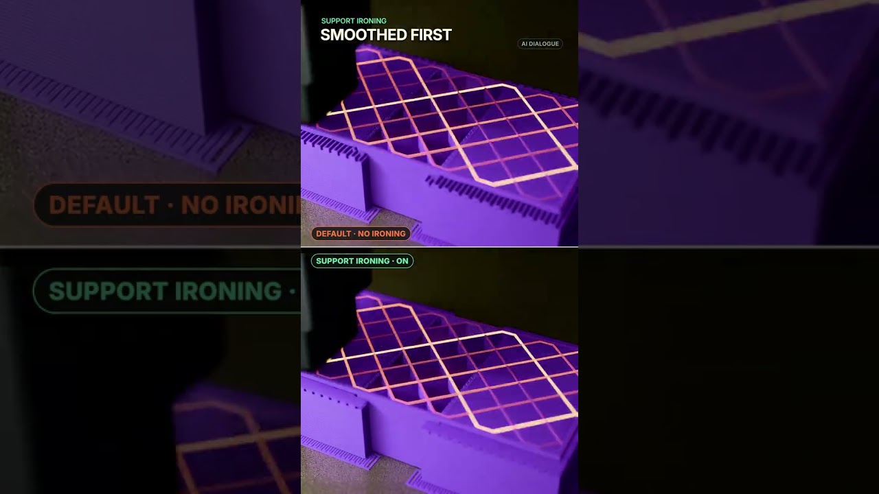
I have also seen that you can “iron” the support top layer for a better finish,
I wouldn’t try that with a support layer.
Why? Just a chance to fail
I haven’t tried it myself yet but here´s the video I watched.
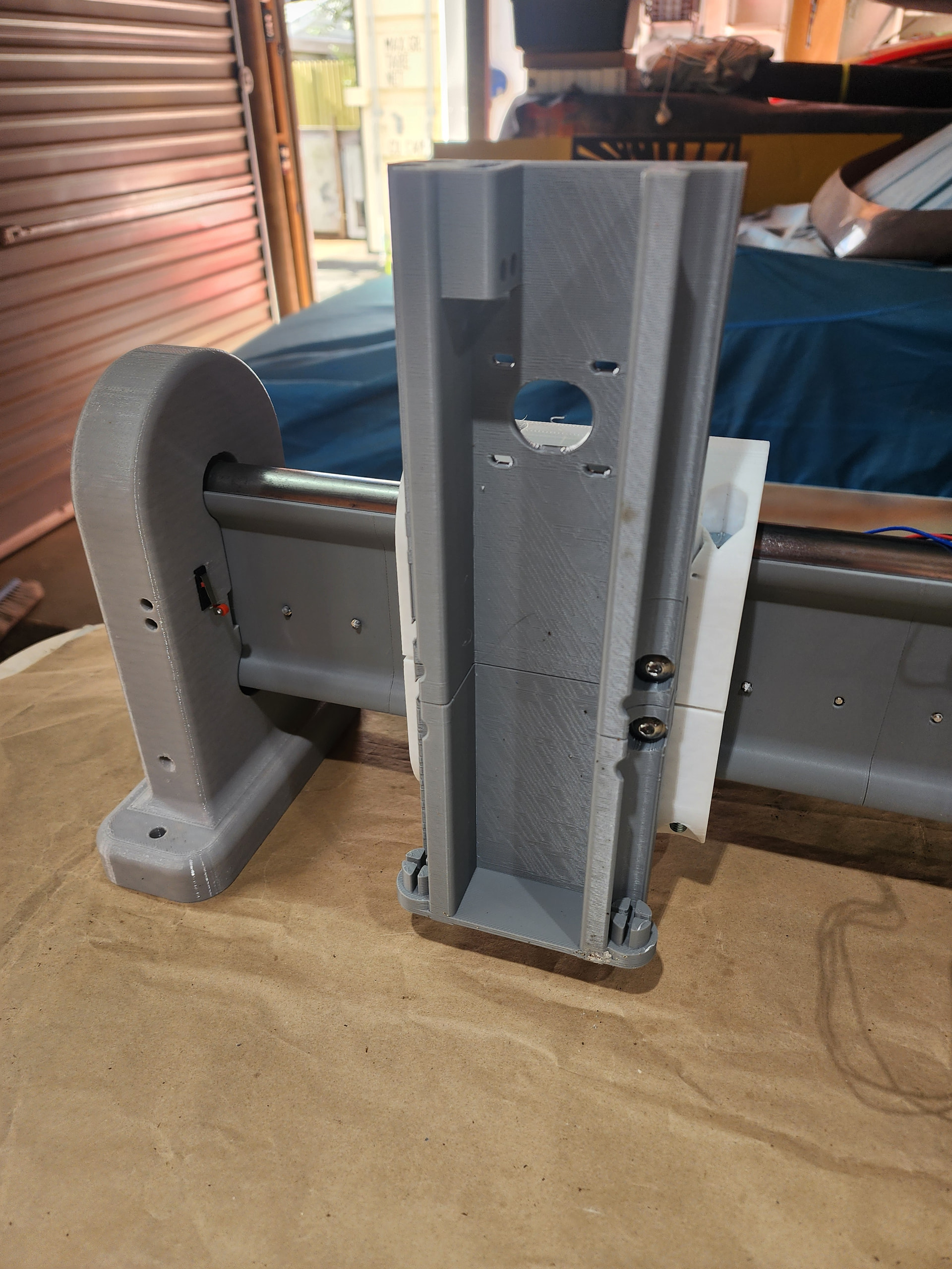
I printed one of the z lifts and than fitted to core
, than realised id stuffed up as to how high the router will sit
now my heads spinning out of control , im now second guessing myself on sso much of it
I need your input please, have I got this right
hope this makes sense
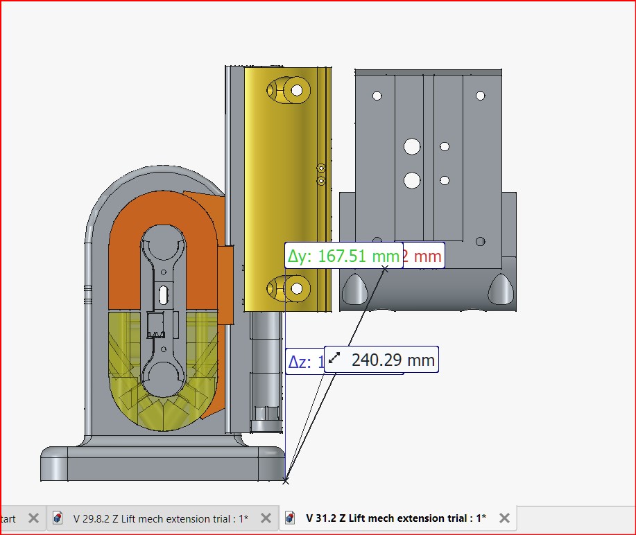
so what ive done is lengthened the bottom of the lift so its 25mm lower.
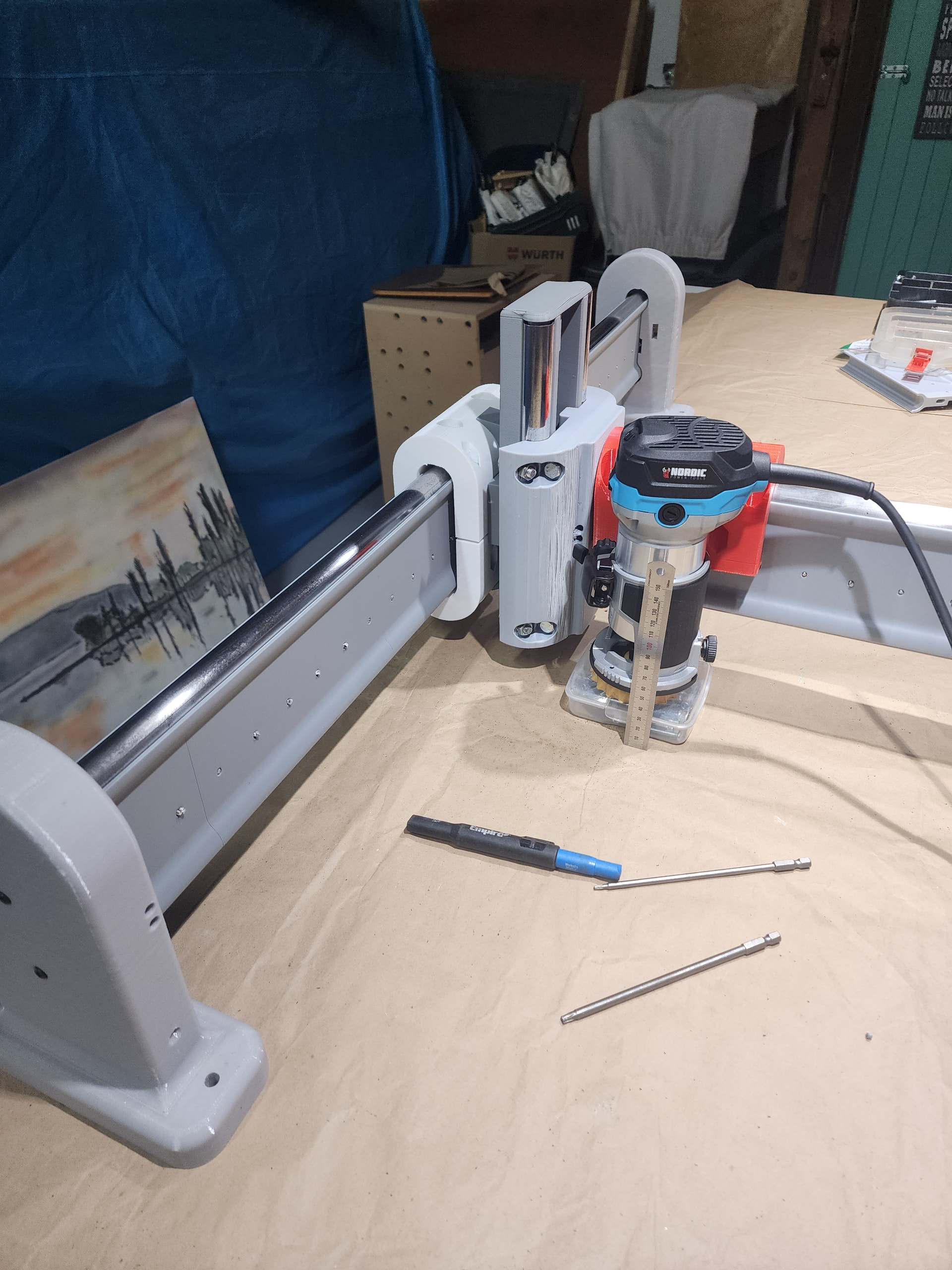
now bottom of x core will be 30mm off table at lowest point , and collet will be about the same.
at highest point collet will be approx. 167mm above table as per image
say slab is 70mm thick , a long 75mm ball nose, stick out about 45 =115 that gives me 50mm free play
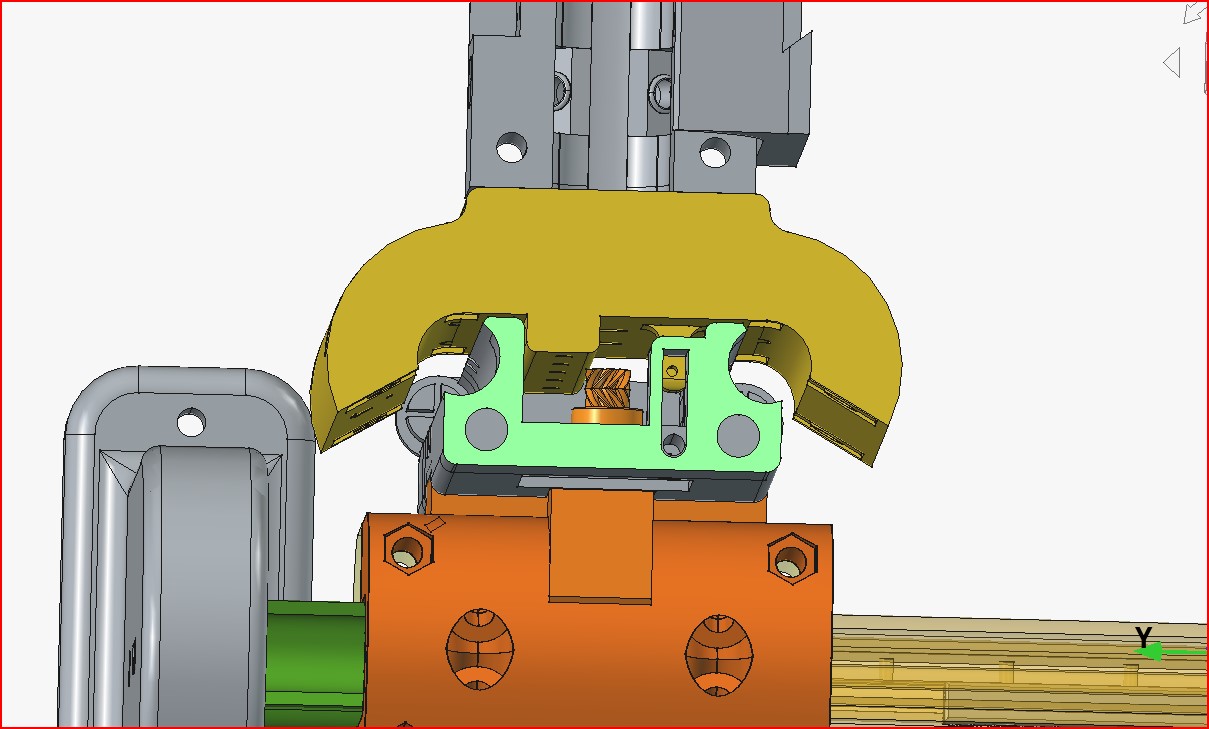
i want try keeps pipes only as high as z lift which gives me 83 mm of travel from Z limit sswitch
to bottom

its main use, will be v carves , and 3drelife carves. max dimensions 600w x 800L height generally 50-70mm slabs or 18mm sheets
If i needed to do thicker slab my plan was print extenders to go under end supports ,
undo 8 bolts put in blocks, re screw to table
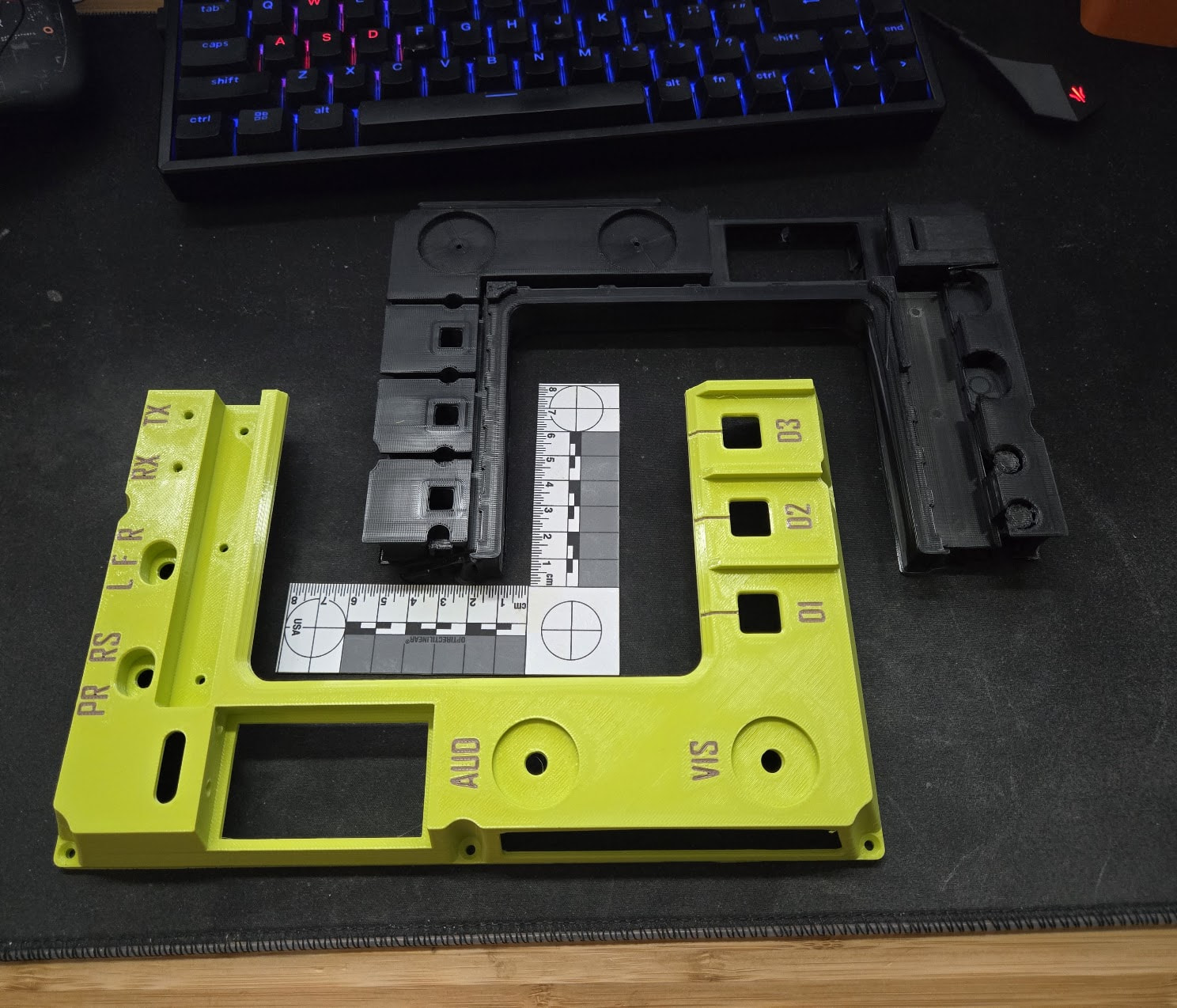
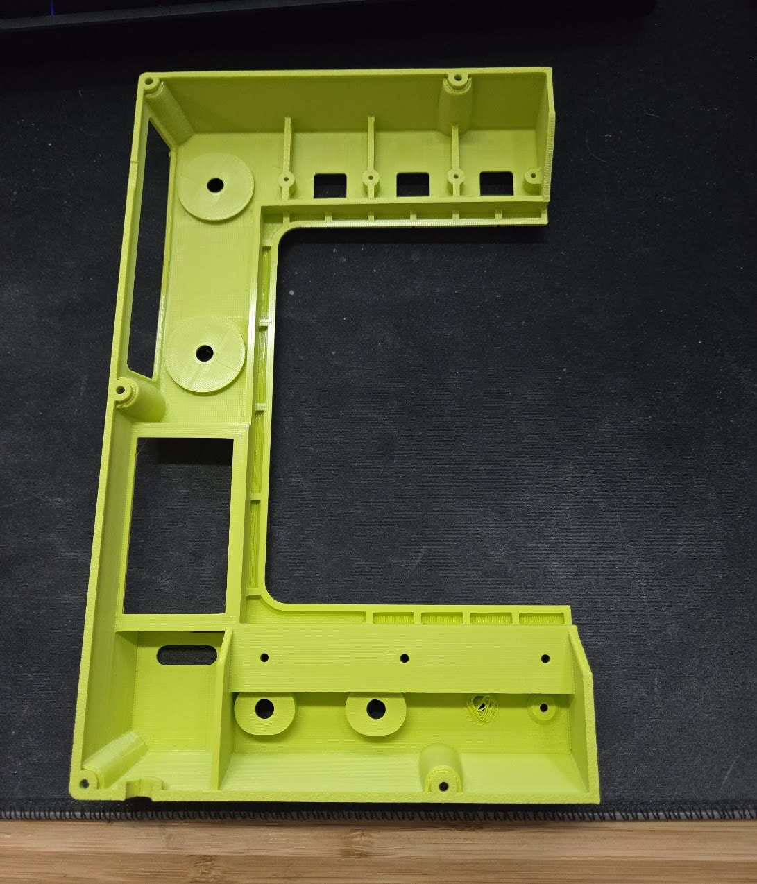

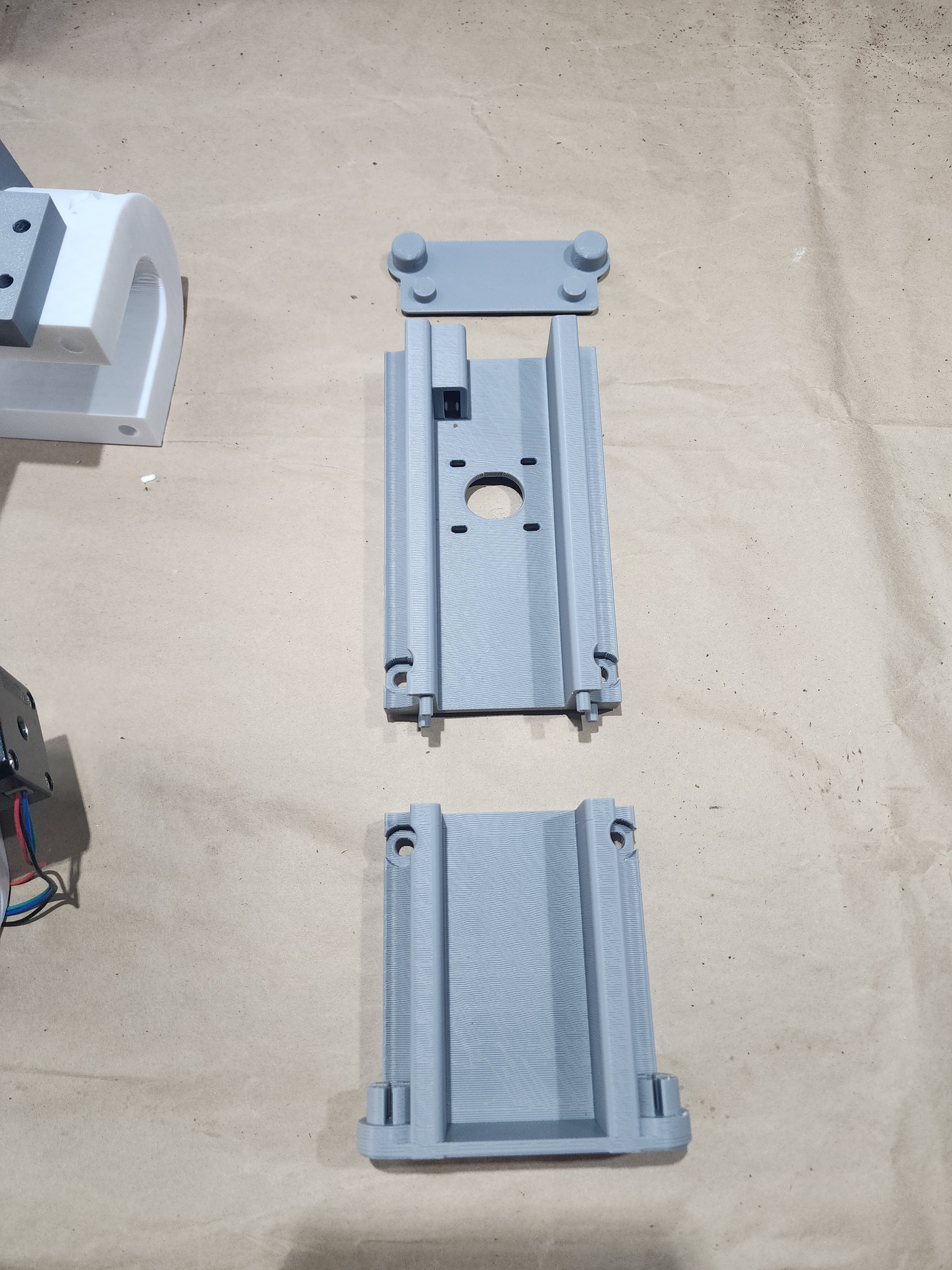
Those are some great looking parts.
Looks really good. Did you design the support as a second part or was that automatically generated?
Those parts look like you are getting prepped for injection molding…you about to mass produce something fun Barry?
i actually tried the ironing on my last couple of prints ,
prints pla, main support, pla , 3 layers of pteg at top of support branches , with zero gap to part , it sticks real well , it dosent just fall off at end of print , you have to physically peel off the pteg
Did you design that yourself? That is nicely done!
Interesting never thought of ironing supports!