Your workshop is more organized than mine it would take several hrs days for ne to go through the Tupperware containers full of random chips sorted by pin count to find anything
A UART is high when idle, if I recall, which is why an AND gate would isolate the TX from each other and forward whichever sender is pulling the TX line low. If multiple senders talk simultaneously then garbage occurs but it is safe electrically.
Also since high is idle, a falling edge (or floating line) generates garbage so you have to be careful with the switching.
1 Like
So, if input 2 was idle (high) and input 3 was transmitting, and low… The idle line would have enough resistance so that the current going from 2 to 3 would be low enough (presumably, because of a large enough pull up resistor) that it wouldn’t let the smoke out? You’d essentially be shorting an output of high to an output of low though, right? If you did that on a normal arduino (SoftwareSerial, perhaps?), that would break something.
No, in my scenario they are all inputs to the and gate. Like this:
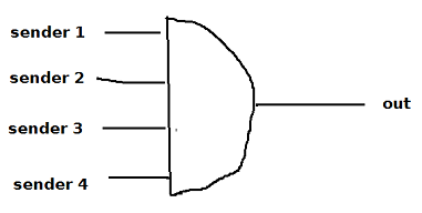
And they need pull-ups or else if one goes away with an open circuit it ruins the channel for everyone.
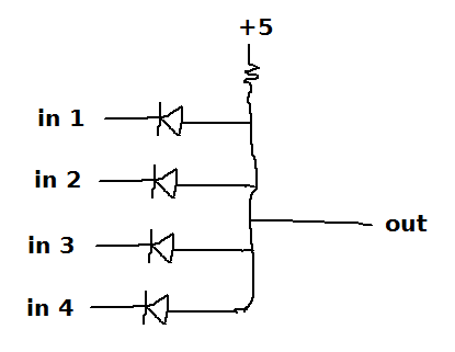
You could implement a poor-man’s AND gate with diodes and a pull-up resistor but it might be kinda crappy since the diode drop means the ouptut voltage won’t really be zero, and there will be extra capacitance, and the output impedance won’t be very low:
How I picture you guys (inspired from my post in another thread):
1 Like
Well, spent an hour doing a quick rewire. Now using the CD4051 8 channel switch (which is break before make). Potentially 8 serial inputs … whoo!
Only connected four of them however.
Yes, you do need to be careful that you don’t short the serial line. The serial data doesn’t like going through a diode (but it will).
Anyway, I’ll amend my drawing at stick that up later. More crap old stock used up!
Glad I could help.
Right. But I was talking about the first wiring diagram.
I am not sure how risky it is overall, since there is some internal resistance, and the bits are only ground for a short period (no pun intended).
Ah, ok, I missed that in the original diagram, multiple can be enabled at once and 2, 3, and 4 disable 1 but do not mutually disable each other. So yeah it seems they would fight each other to some extent.
Looking at it again now, there might also need to be a pull-down on pin 1 of the 4001 IC, or else floating (or even low) values on the other channels could leave serial 1 disabled.
OK. Version 2 now up and running. I should point out that I test these on my bench with spare Arduino’s to ensure it all works, before committing it to the CNC installation.
Same PCB, just a slight rewire.
This switch is break before make, 1 gang, 8 way. Only using four of the inputs. Seems to work well.
4001 Nor gate not really needed. But as it’s there, it is just used to illuminate a ‘default channel’ LED indicator.

Tidiness is your friend…
7 Likes
This is even better than mine it’s more on your level @turbinbjorn Do you have a map and aisle numbers
1 Like
Wow @stevolution , that is so smooth and responsive! I can’t beleive this is running on Marlin, I will have to try to duplicate what you have done here.
I have this PC Flight joystick, (Saitek x52) that I don’t use much anymore, wonder if I may be able to use it. Would be so cool to tie into the extra buttons for custom commands!
Oh, and don’t give up on your MPCNC, you seem very talented, and that is a wicked looking setup you have.
