It has taken much longer then experted to learn all the nuances to even get a first cut. What a deep learning curve this is. Even to get something basic cut.
I spent way to long trying to get FreeCAD to work. I really wanted to use and support open source but it’s just way to buggy and the documentation is pretty bad and missing context. That along with not really knowing what I am doing was too much. Finally gave up. I spent WELL over a month on this. Bah!
TinkerCAD. Quite the cool little capable tool once you learn some of those secrets. Ultimately, 2D and inkscape won. With inkscape I can keep the paths separate paths which helped with paths. With TinkerCAD it merges them down to a single path which did not work for what I was doing.
I also tried to figure out how to download fusion 360. What a mess. There is no “personal use” option only business or educator. The download never does anything. I had to open a support ticket and nobody has responded and the trial clock is ticking. Oh well…I guess I can’t play with the cool kids.
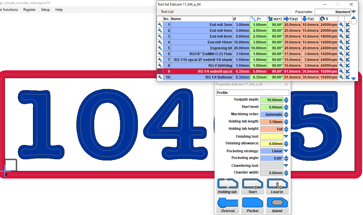
Back to ESTLCAM, since it was recommended. It is quite clunky and yet quite capable. Lots of secrets. Oh parameters for multiple materials. Oh you can delete paths. Oh you can pocket between the separate paths of an O. Still a lot to learn.
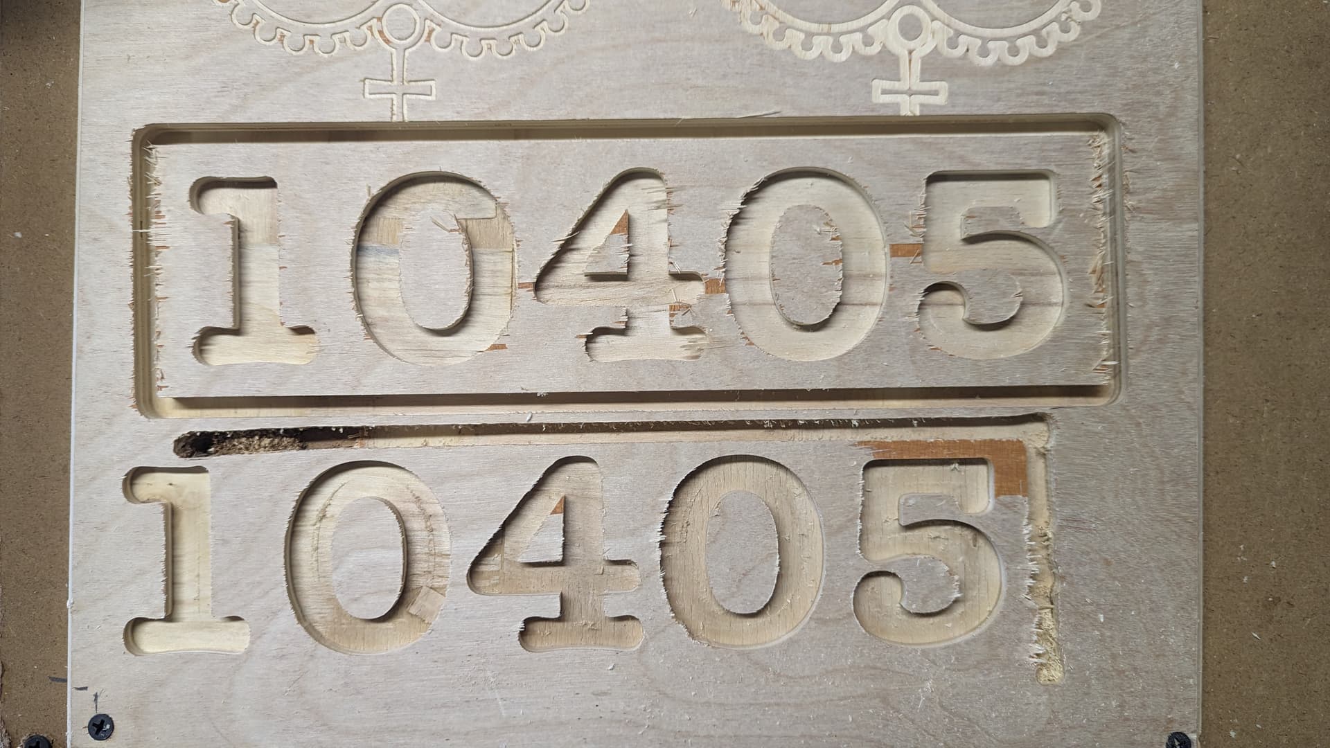
Finally, on to a SIMPLE project. I’ve tried many “simple” projects, but there is always a gotcha that isn’t so simple. E.g. A square with a notch and you can’t cut out the entire notch with a hole path. I am finding nothing is “simple”. Anyhow, I decided to make a house number sign. A square with numbers and profile the edge (like chamfer but using bullnose for flourish). In the end I abandoned the bullnose since I was having issues and the toolchange was yet another “problem” to eliminate. Geez.
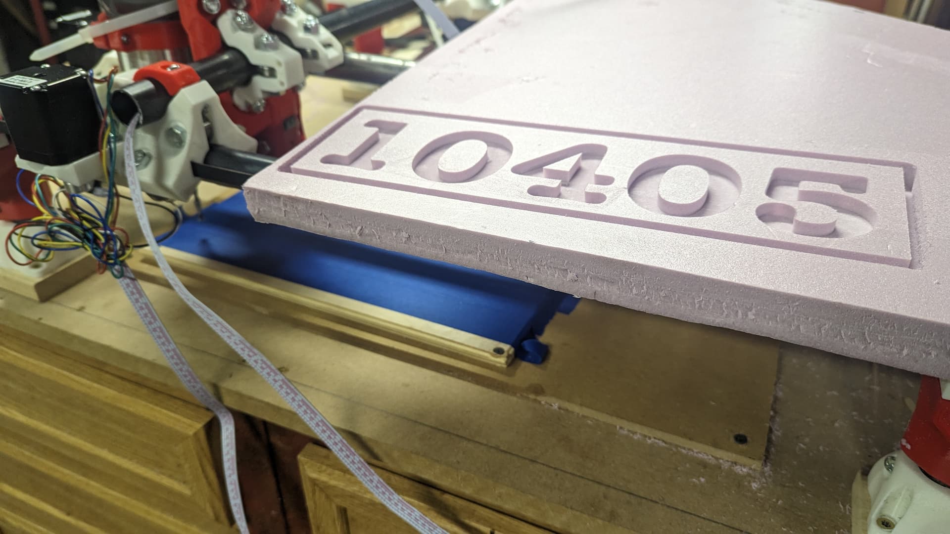
So finally I get a reasonable ESLTCAM output and cut the house sign out of PINK Foam. But I had split the job into separate paths. 1 to a file. So I could run them separately. I think that was a mistake without editing. But it may have been a misunderstanding about coordinates needing to be reset (more on that later). When I ran the SECOND file it went wonky. It cut into the work piece from the wrong direction (did I miss something?) and went to the wrong depth. Uhg. So, I got rid of the bullnose path dressup and kept it even simpler (if boring) all 1 bit in 1 gcode file and it cut great in Pink Foam!
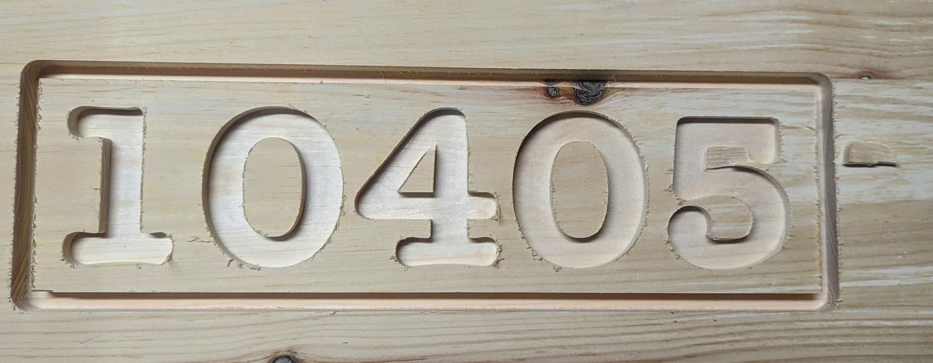
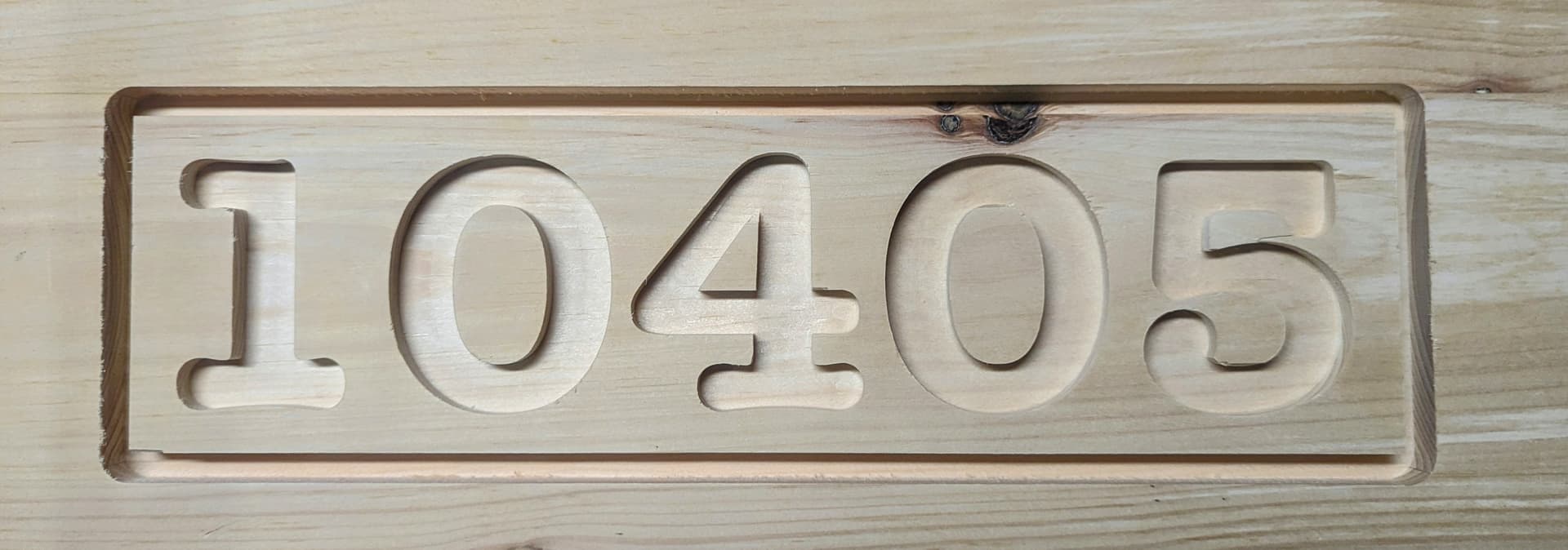
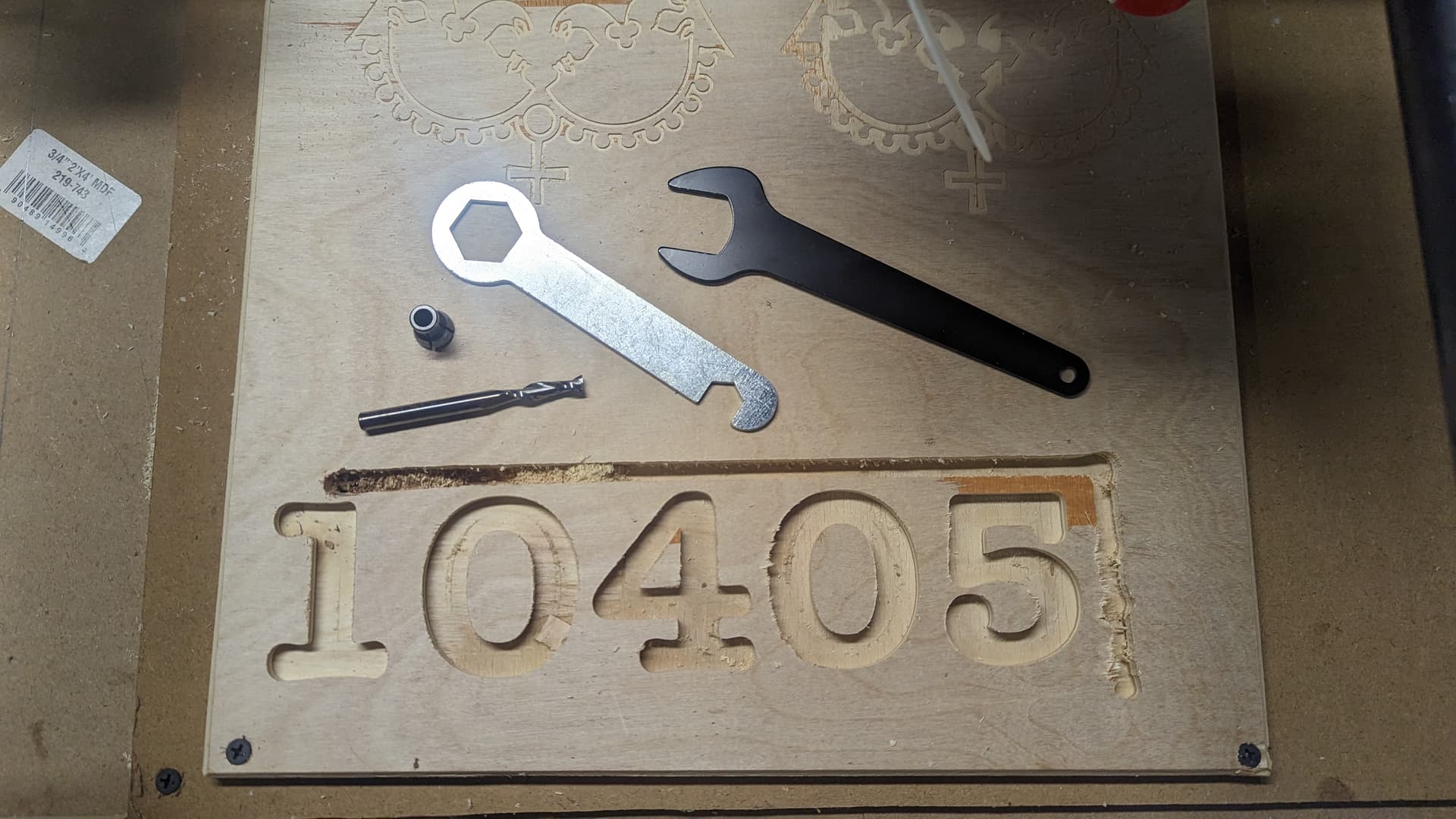
I had carpet tapes the pink foam on top of my actual work piece. So, when I went to cut my actual work piece, I set my Z height to the top of the wood, assuming it would start from wherever I put the Z. Nope. It raised up and was cutting air. Grr. Took a while to figure out “RESET COORDINATES” on the LCD. Finally cutting wood. It cut the numbers pretty well but the outer boarder sounded like it was struggling and went wonky and the bit actually came out of the collet. Doh! Close but no cigar.
Thoughts on setup for this outside profile cut? Is anything too aggresive or do you think it was just the loosened bit?
Details:
1/4" UP cut endmill. SpeTool 1/4 Dia 3 Inch Extra Long CNC Solid Carbide Up Cut Router Bit
Plywood 12mm, really thin layers fancy baltic like face. I assumed this as Hardwood but laminate is even faster. You can see how thin the ply face is as it pulled off when I removed the masking tape. Masking tape did not do well. Sounds like folks use oramask?
10MM Toolpath Depth (2mm left instead of tabs)
6.35mm Depth Per Pass
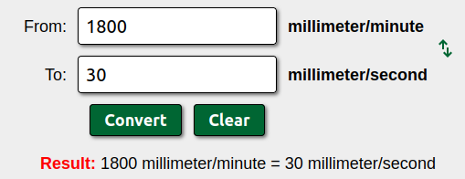
91 mm/s(215 i/m)
stepover 40% (but not in play here)
The profile path was in fresh wood (all sides of bit touching wood). The path (Not rotation) was going counter clockwise around the board, and it was struggling. Does direction matter here? I can’t change rotation on the Makita clone AFAIK. Rotation is still confusing and I don’t find much concrete info yet.
Tighter bit (of course) but what else?
Ramp Endmill 45?
Slow the feed? 85mm/s?
Depth of Pass 5mm?
what else?
Thanks
Rick