Somehow, I find the idea of a robot with a sextant intriguing…
2 Likes
A: Those are Sealed lead acid batteries, not much worry about spilling em’
B: In my experience battery acid is pretty weak. Doesn’t really burn when you get it on your skin, just sort of itches. I’ve never suffered any Twitch ill effects Twitch, Twitch, I swear. 8^)
3 Likes
I have found that all of my successful personal projects have 3 things in common: blood, sweat, and tears. If I get to the end and haven’t achieved the trifecta, I figure I missed something and hope no one else notices.
2 Likes
There used to be one that had little ir modules you could put in rooms that would shine a constellation on the ceiling that it used to find where it was.
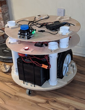
Progress. Base/Motor/Charger plate is assembled with PVC supports glued in and installed. The middle plate (power plate and motor controller) is assembled with some glue drying on the PVC supports… I transferred the wiring from the old robot so I had to lay it out a bit funky to avoid having to remake wires to get make them longer. Does the Job™

I went ahead and crudely mocked up the top plate (the brains) and added in a surveillance camera to see what it might look like. I have an RPI4 that will work with the kinect to do the SLAM and a jetson nano intended to work with a surveillance camera (not that one… its old and low res) for object recognition and maybe face recognition.

2 Likes
Doesn’t the kinnect have a camera too?
Yes, but I want a separate camera for a few reasons… first it’s easier to get the images to nano if it’s connected directly to it, especially for development purposes. The nano has two rpi camera inputs so I might use pi cameras. But more importantly, I want it on a pan-tilt platform that is independent of the robots orientation.
1 Like
A bit of a catastrophic failure in the drivetrain. I used a flexible 8mm to 12.7mm coupler to go between the motor shaft and the axle and it snapped. It was one of those spiral-ish ones and I guess it was out of alignment enough and under enough strain to cause it to fail. It was ‘cheap’ in all sense of the word so I ordered new “jaw” ones…
It seems that I probably should have used those in the first place.
Just make sure you don’t try to drive it past the hard z zero. It will uncouple itself.
You’re going to have to explain that a bit further… hard z zero?
1 Like
All the way down to the table. Once that happens, if the motors are still trying to lower it more, it will decouple the halves of the coupler. Which is better than stretching the spiral ones, but make sure they’re tight again before cutting.
Oh, these things are for my robot, not the lowrider… they will couple my motors to my wheels.
1 Like
Ahh! In that case, carry on!
2 Likes
So, I seem to have a bit of a problem with stretching the spiral couplers. Strictly operator error, but I’m starting to think I should order them by the gross.
Out of curiosity I ordered a couple like those linked. I’ve encountered similar couplers (“Lovejoy” couplings) in more industrial settings, and like @barry99705, I thought they would decouple if “stretched”.
The ones I got, however, fit together TIGHT. They will not decouple without significant force. I’m afraid to put them on my Lowrider, because I think something else might break before they decouple.
Lot’s of set backs and progress. I burnt the motor controller (both drivers on it) trying to adjust the PID so I ditched the software package and switched to a different one I found (linorobot… wish I found it first). I used one of my many Maslow CNC 3-motor controller shields to drive the two motors and when I needed to hook up the IMU, I had to get access to +5V, GND, SCL and SDA. Through some really strange serendipity, those very pins happen to be wired out to the third port of the motor shield (pins 20/21 are used for the encoder for that port and they just happen to be SCL and SDA)… planets seldom align this well. So I have a very tidy installation now and eliminated a spaghetti nest of wiring.
But, the problem I’ve run into is that the new 1/2-inch to 8mm couplers don’t have set screws and just clamp down instead. Unfortunately 1/2-inch bolts don’t seem to be precisely 1/2-inch wide so it doesn’t clamp tight and the wheels slip. I’ve wrapped some plumbers tape around the thread to build it up some, and though it feels tight, I still think its still slipping under the stress. I’m nervous about testing it by hand and breaking a gear or something. I’ve got to dissemble and try some more, but I might just epoxy the thing in place. I’ve yet to see a 1/2-inch to 8mm jaw coupler with set screws.
1 Like
I have shimmed couplers in the past with pieces of soda cans. Pretty even and thin, easy to cut.
I dissembled the robot a bit (glad I used threaded pvc couplers considering how many times I’ve taken it aparr) and it was the other wheel, the one with the spiral coupler that hasn’t broken yet, that was loose… The set screw to the 1/2 inch bolt had loosened up… so now it’s tight with threadlock applied. But, thanks for the advice… I hadn’t thought about that and seems like a good solution. Will try it when the spiral coupler breaks.
Bit of an update (also, I’m a bit excited)… I decided I was spending way too much time farting around with IMUs that I couldnt get to work and a Kinect as my laserscan that only looks in one direction. Combining those two things together made mapping really frustrating. So I put down some money on a laser scanner with integrated mapper/imu (slamtec mapper m1m1). I redid the launch files so all the raspberry pi was doing was processing cmd_vel into motor controls, which is gross overkill for an rpi4. On my dev machine, I ran the ROS mapper launch file and the mapper does such a good job that I don’t even need to feed it encoder odometry. Between the integrated IMU and the lidar unit, it produced this:
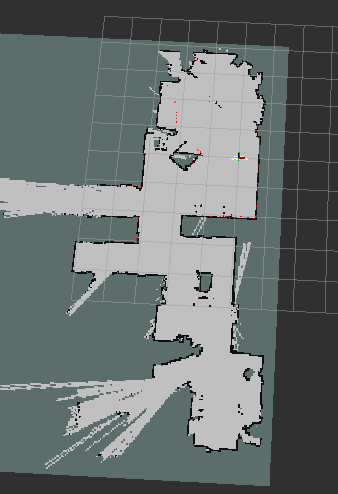
This is very, very representative of my family room and kitchen area. The only one problem is that where the lidar is mounted, it’s a tad high and its shooting over the couch cushions and a large ottoman. Nevertheless, I’d rather overcome that problem than all the other issues I’ve been dealing with.
Unfortunately, the ROS SDK for the slamtec mapper is x86_64 only… so it doesn’t run on the RPI. I was hoping to make the robot self-contained so I’m looking for a cheap option to run the SDK on the machine.
I was thinking perhaps an atomic pi and then run the motor control on that as well and repurpose the RPI4 for another project.
3 Likes
Is the nvidia tegra soc x86_64? I think it is $99, and it would have a lot of potential for computer vision or machine learning.
I have a nvidia jetson nano, but its arm. I think all the tegras are arm as well.
I was able to get move_base running and it had no problem processing the map, scan, and odom messages the m1m1 was publishing. I was able to use rviz to set 2d goals and have it plan a path and move accordingly but I need to get the URDF built because the laser scanner is not where it thinks it is so movement is a bit off. I did run into problems trying to use amcl and map server (to use a saved map)… I think it has to do with the transform tree or something… things I’m still learning about.