We still need a good top level description for it, but K nailed the basics.
It’s here, and there are some “releases” linked there. v504 is what we’ve been trying to test, and hope that it is stable enough to get rid of the “prerelease” flag on it.
Once that is stable, I’d like to play with laser and/or spindle through a relay control. Ideally, it would use the fan port, and enable M3/M5. Then I need to crack back open the TFT code and give the user the ability to choose M106/M107 or M3/M5. But, I have a real job too, darnit.
Yeah. I saw that, I’m not sure why but I thought there was more I had to change. I never really found a thorough answer online. I never really did any testing myself either though, I don’t have a multimeter yet but will probably order one towards the end of the week, along with the new spindle and rest of electronic dodads to make speed control work.
I could totally use M106. To do that I’m pretty sure I wouldn’t have to change the firmware at all, but I would have to change the post processor, and that I don’t care to do when I could have a supported spindle gcode anyways.
A bunch of parts for a work project came today, this project will be utilizing the mill which I’m pretty excited about.
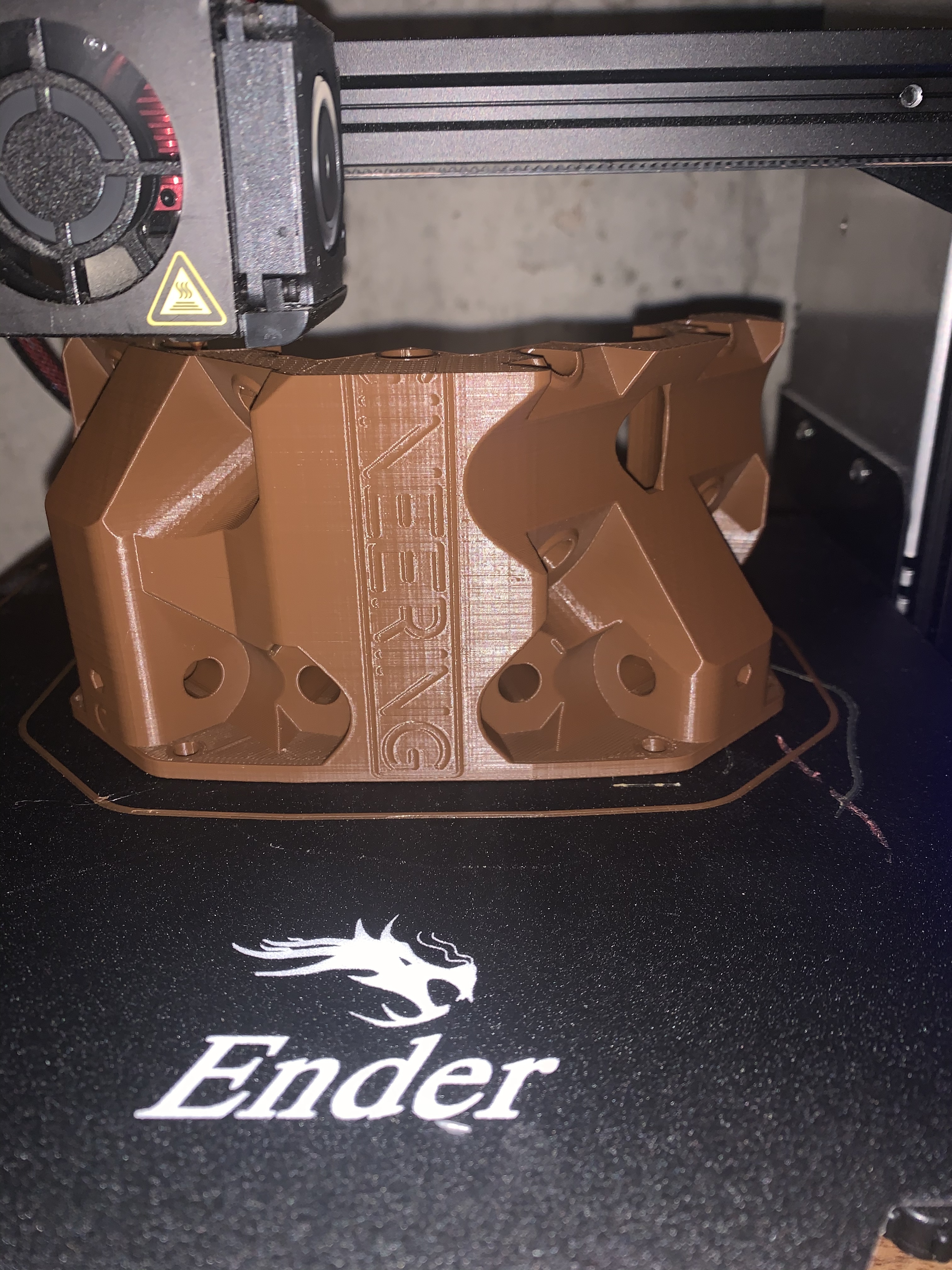
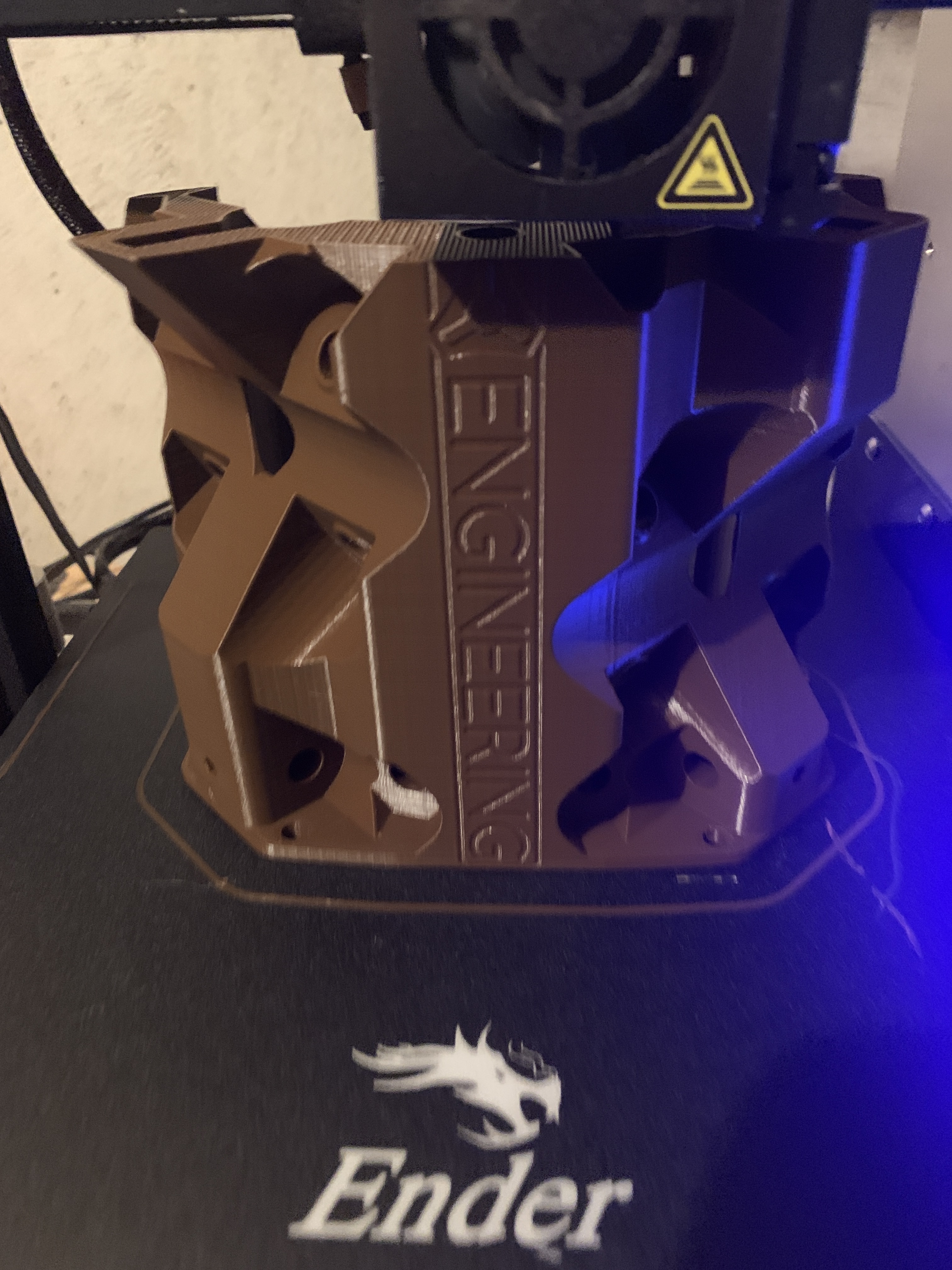
I just finished printing my Primo 23.5 core last night. 37 hours total. What I figured is that the profile I was using was optimized for quality/detail, but these are structural/functional parts. I have switched to a 0.6mm nozzle and trying different settings to optimize for speed. Will report once I get a better handle on the settings, but switching to a 0.6 nozzle and increasing layer height (I’m using 0.4 = 75% of nozzle) is the biggest win.
I was imagining that being a good place for a plate, unfortunately the holes are not universal on all the cores. I intended to come up with a blank plate people can use for things like vac mounts. Your air blast might be best mounted to the core clamps, or on the actual router. You don’t want to make the build any taller than absolutely necessary.
Well, they have a cnc now, so even if the holes are a little different, they can cut something to fit.
A lot of people don’t have 3D printers and order the parts from you. So hopefully someone will think about them and give them a thing or two to cut to add some stuff to their mpcnc. That would be fun.
Given the hole patterns on all the cores, I probably could make something. I have an led strip, not one of the flexible ones, maybe my mill needs a light.
It’s supposed to hold and spin a ring, and it has a solenoid valve to run a glue gun. It’s just supposed to speed up an assembly process, it didn’t go perfectly but it should work pretty well.
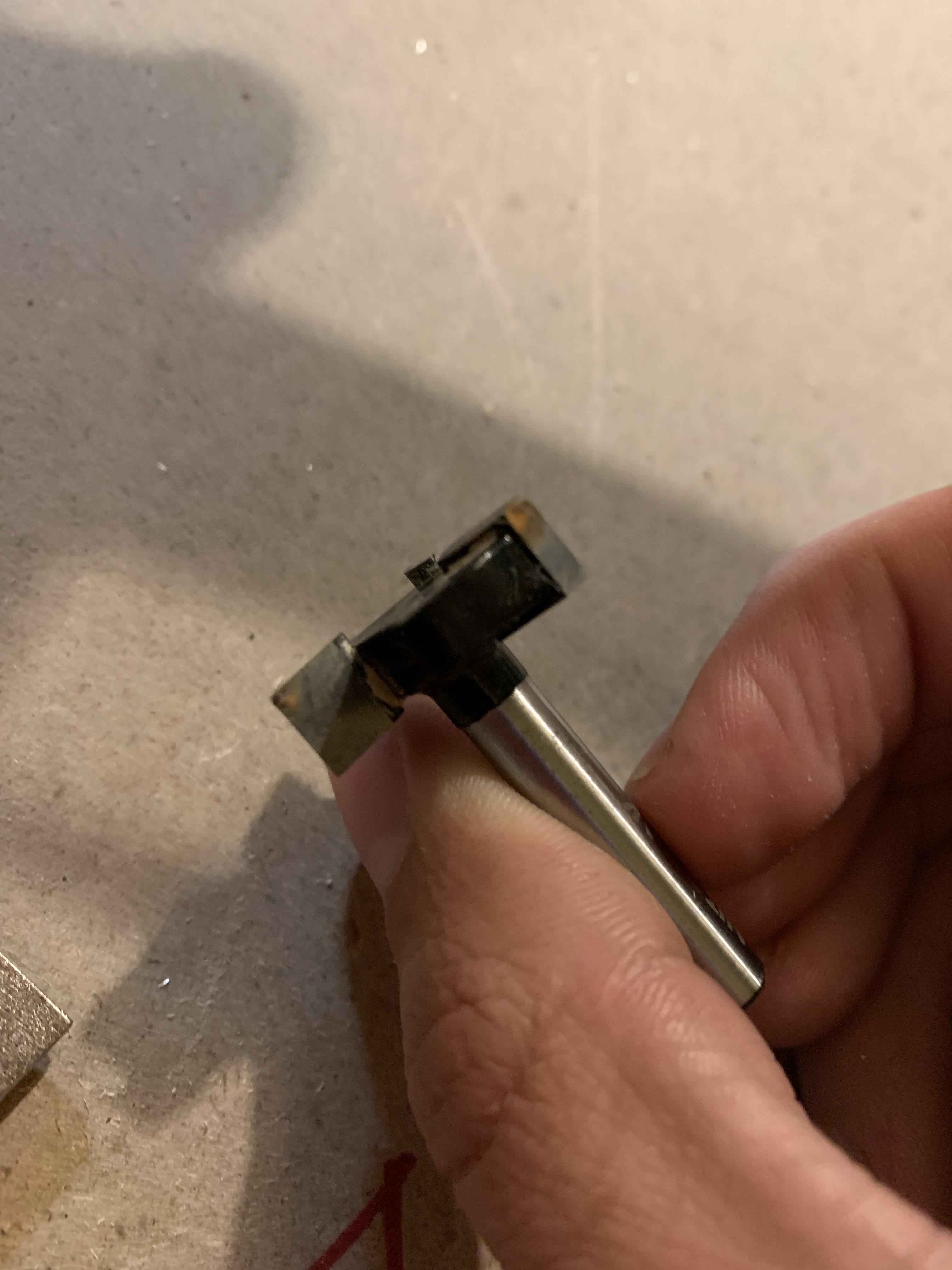
When looking at stuff for a project, I saw this on a face mill i used to level my spoilboard.
To me it seems to be burnt up, and also seems to have a bur rolled over on one or two of the cutting surfaces. Is this cutter fine? When I did surface my spoilboard I only did half of it because the DOC was getting to large and the spindle was bogging down. I also accidentally set the ramp speed to the same as the cutting speed.
I recently bought a pair of airpods and I kept seeing the silicone cases for them and I thought it would be really cool it you could make one out of aluminium. I could not find one that was just a plain aluminium case and something sleek and simple. I decided I would try and make one. There are a couple problems looking at how you make this, such as how you hold it being a round shape, and how you mill the inside pocket. To hold it milling the outside profile I’m going to drill and tap two holes into the stock and mount it to a plate that can be drilled down. To hold it milling the inside pocket after the outer profile I plan to make a kinda box that just fits it that I can screw down to the table. The next problem of milling the inside pocket is you have to reach to the bottom of it, which on the bigger piece of the case is probably 1.75". That means you have to have 3.5" of travel because you have to use an endmill that long. I already checking my machine and the z height is fine, the only problem is going to be problems with long endmills and rigidity. This project is obviously more advanced and I’m going to wait a month or two so I can get more experience. I think it would be really cool if it works out and could maybe make some money too. It would also be a great showcase of the MPCNCs capabilities.
On mill upgrades I recently ordered everything for the new spindle and speed upgrade. I also am pretty close to the new core and the leadscrews. I’m going to do both at the same time, and add a drawer for the control laptop, and move all electronics under the table.
I am super closed to finishing the leadscrew upgrade, I just have to reprint one part that printed weird. This is something I have been wondering about and will soon be able to test; is the problem with rigidity on the MPCNC the conduit or the belts? I understand this is already somewhat documented here with testing on the conduit and people buying DOM tubing, but that doesn’t really make sense to me. When an endmill chatters, doesn’t it chatter side to side? So does that mean the tubing is flexing side to side? To me it seems more plausible that the belts are flexing. As soon as any cutting load is applied to the cutter, wouldn’t the pulley apply a load to the belt and stretch it, creating somewhat of a rubber band, ready to bounce around? This is in no way a real criticism of the belts or Ryan’s design, they clearly work well, but could the MPCNC perform better without the belts. I should be able to see soon for myself, probably within a week from now.
At this point it is either the printed parts or the rails all depending on build size. The belts are kevlar or fiberglass reinforced and effectively do not stretch under the loads we use them.
The printed parts flex, as do the rails…size determines which ones are a bigger issue.
No/yes. It moves in any direction, including up and down. The endmill is at the end of a long stack of components that all have some level of give…the endmill itself could also be the issue if you have too much stickout, router runnout, loose bearing. Think about the stack for a second, floor, table, feet, legs, corners, rails, belts, pulley, stepper, trucks, core, bolts, bearings, rails, tool mount, tool, collet, endmill. Put a plus sign in between each one and start measuring deflection.
Unfortunately it is not as simple as “let’s use $100/ea screws and the machine will be perfect”. This is a system and each part has an effect. If it was that easy every CNC would use screws, screws are actually a very poor choice, until you get to balls screws and then you need to have deep pockets and a solid understanding of tension/backlash and maintenance.
So bottom line is the biggest factor is size for every CNC ever, from there it gets complicated.
I understand that it is not as simple as that, but it could help. The only reason I’m doing this is because I have these screws, I probably wouldn’t have bought them had I not had them. As the for the actual stretch of the belts, I found somebody who has tested it. https://imgur.com/a/gIk2J They tested a belt from ebay and a belt used on the anet printers. It doesn’t seem like a ton of flex, but in our application even .1mm could cause a significant loss in rigidity. I understand $100/ea leadscrews may not be an option for everyone, but I have them and am interested in whether or not they will improve the machine.
How long of a belt is that for, and how wide I am assuming 6mm gt2 which is rated for ~30N So that graph is completely understandable that 10x the rated load it fails. A 3d printer probably only ever experiences a few Newtons at worst. The Primo uses 10mm belts.
Everything moves. Belts have very little slop/backlash they do have some degree of stretch but very linear and minor under proper loads. Screws have slop/backlash that can possibly be tuned out but changes over time and needs careful maintenance, but little stretch (bending when properly supported) which also brings up Whip, speed, and friction.
x5, it is not an option.
Technically if installed and geared properly, yes. Noticeably, probably not at all. I do not feel the belts are a significant weak point. Remeber steppers have torque speed curves, make sure your screws are a proper gearing and slap them on. Show us how it works. We would all love to see a super deluxe build.
I am in no way discouraging this, I just absolutely do not want people to think doubling the cost of the build will improve cutting speeds in a very significant way. If I am wrong and it does…I will offer a “pro” kit and let people choose how they want to spend their money.
I know I haven’t updated on this in a while, this build is not dead. I’m pretty busy with school right now, but I almost have the mill ready to run, on its new leadscrews. I am also working on a video about it too, so I will post that once I’m done with it to display it’s functionality.
https://youtu.be/cbBk1ixjJ00 I finished the leadscrews and made a video about it. The problem I mention at the end, after looking into it, I think could be electromagnetic interference. I moved all the electronics under the table, maybe somethings close to something it shouldn’t be?
How many steps/mm are those screws running, and on what board/drivers? Cutting speeds and rapid speeds for X&Y? There is a limit and I think you are exceeding it or running right at it. So it didn’t necessarily skip a step, more along the lines of it just didn’t even try to do it…if my theory is right.