OK, I will try to replicate.
Can you shoot a pic or two of the overview of the setup, just for added clarity, especially if others try this?
OK, I will try to replicate.
Can you shoot a pic or two of the overview of the setup, just for added clarity, especially if others try this?
So we should lead line the carriage?? Lol! Joking of course!
My phone is being stubborn about uploading photos to thenforum, unless I use the camera directly.
Really nothing special, and so long as you measure “before” and “after” in as close to the same conditions as possible, the results will be valid. The exact same results aren’t likely unless you have a 32" gantry with 1.25" 0.065" wall DOM steel. What I think matters is the before and after relation.
I would think a longer gantry would show more deflection. I think smaller tubes will show more deflection. I think a tighter fit of the tube to the brace will show less deflection. I think a rougher surface on the print will show less deflection. I think stiffer brace material will show less deflection.
A tighter fit of the brace to tube, and a rougher print surface probably means less change for the screws to the braces, but may not affect the strut to tube ratio, but that’s just postulating.
I am skeptical of this methodology, because I suspect it might be measuring something that is not closely related to the performance of the machine.
The torsion of the beam is supposed to be supported at both ends, and by measuring the resistance to torsion when loaded at one end, it’s not measuring the same thing.
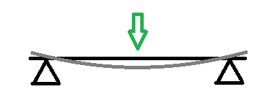
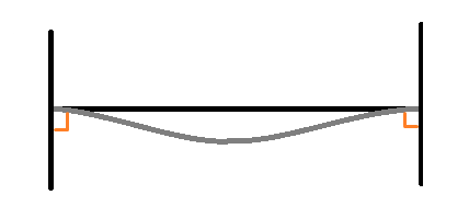
If you have a beam that’s supported at both ends and you apply a load to the middle, you are measuring the stiffness of the beam.

If the supports are not pivots then you are measuring the stiffness of the beam plus the strength of the ends of holding the beam perpendicular (illustrated in orange).

If the beam is supported on only one end, then there is also a combination of stiffness to bending vs stiffness of the joint, and the deflection might look very different if the bending is much stiffer than the join or vice versa.

Left shows the case if the joint is very stiff and the beam is flexible. The right case is if the beam is stiff but the joint is not.
This is all an analogy because we are actually looking at torsion, but I am claiming the same rules apply to torsion.
I guess my claim is that the stiffness against twisting the ends relative to each other is less of a contributor, whereas the torsional stiffness against both supports is the dominant factor in the performance of the machine.
By removing one end and measuring the deflection, you’re measuring something that is very different from the stiffness that matters.
As an extreme example, imagine if you removed strut plates and all braces and just had two extremely strong tubes and nothing else. The stiffness against twisting the two ends relative to each other would be effectively zero, but if both ends are supported, twisting the center requires bending the tubes, and the stiffness to torsion can be much higher.
The actual machine is not so extreme, but I suspect that supporting against single-ended twisting is very different from the torsional stiffness that matters to the performance of the machine.
Perhaps you could try the sanity test for machine rigidity I’ve suggested before:
Dial indicator in a holder pressing against the back of the router collet nut. Fish scale hooked onto the router tool at the nut. Apply 1kg of force and measure the deflection.
That’s what I did with my MPCNC ages ago and it was pretty telling. It was easy to see the deflection change significantly with position (as you’d expect on the MPCNC).
That should be about as close of a measurement for machine ridigity as possible and could be an easy way to verify whether the toe lift test directly translates into usable cutting rigidity. If it does then the toe lift test is a hell of a lot easier to do quickly and without any additional equipment.
I’d love to, but I don’t have a dial indicator. I have to make measurements with calipers. I did a click test in which I tried using a luggage scale to pull the collet nut away from a wrench. On the 32" beam, left, right or center I wasn’t able to get the nut to click when releasing tension with less force than it took to make the Y motors skip. (In two cases, I pulled one or both “heels” off of the table/rail.)
As such, I can’t guarantee that this actually reinforces the machine in a way that affects cutting.
I can (and I believe that I have) shown that my beam was able to twist before, and that it twists less now. I listed some factors that I believe would affect this.
I have a couple of cheap dial indicators from aliexpress that are worth having around. I wouldn’t trust them too much but they’re surprisingly good. Similar situation to digital calipers, surprisingly good and accurate for the money.
So by click test you mean deflect the collet nut far enough that when released it ‘clicks’ against the wrench?
Something like that would be my 2nd suggestion, put an item a fixed distance away using a shim and see how much force is needed to make it contact. Could even use the touch plate to indicate contact.
The other way to do this without a dial indicator is pull the collet with a scale to a fixed point, then see if it gets harder with the glue.
This test is pretty tough, I am not sure how best to actually check it. I would want to lock the YZ plates and pull on the collet while it is in the center of the beam. In Y, and even in X to see if either changes. X might prove it helps against sag, Y torsion.
It is definitely doing something.
Is there a specific issue you see with the DTI + fish scale approach that I used? Admittedly that was on the MPCNC, not the LR, but I feel like the approach should be valid either way?
Talking about the twisting of the entire machine yes, the glue reduce the amount of deformation, cause there is a shear between the tubes and the plate. But the core deflection I think is a completely different type of deformation, probably it will help, but not so much. In this case the rigidity of the plates themself is more important. In few days I’ll replace the strut plates, from 5mm HDF to 5mm 6060, I’ll test deformations for both the configurations.
1420mm gantry, 30x1.5mm tubes.
That is how I did it from burly to primo so I agree with it. It tests the system as a whole.
Very interested to see this. If you don’t mind adding a test pull with no plate at all that would really help. I have theories, but some real numbers would be cool.
So this twist test is interesting.
What if there were a strut plate front and back?
How you going to make a curved plate for the back?
We still have another feature that is untested, tried, but untested. Let’s see where the plate and silicone glue test get us first.
I was talking about immediate back, but i think i forgot there are stiffening braces there!!!
Taking a step back. I think aluminum and steel has been cut now! Has anyone observed twist while running? The unit, (i think) is heavier than the lr3. I would like to believe the twist will not be there.
The test is extreme, and there was little deviation. ( to me there was little deviation).
ACM panel they come in 3-4-6mm and easy to bend in a roller. These 4mm european (spain) brand stacbond are superstrong
Ook!
Alu Plates have arrived!
I’m trying a reliable way to test the deformation, but is not easy. The ratchet strap isn’t precise to apply load.
This is the first attempt:
Wow, that is not much movement. 10kgs of load while cutting and you have majorly f… it up, so I think we are good. ![]()
10kgf of cutting force is close to what you will work.
On Plywood: 6mm endmill single flute, 6mm DoC, 1260mm/min @18k rpm generates 6.8Kgf
Hmm, interesting. I thought the load would be much less because it is actually removing chips.