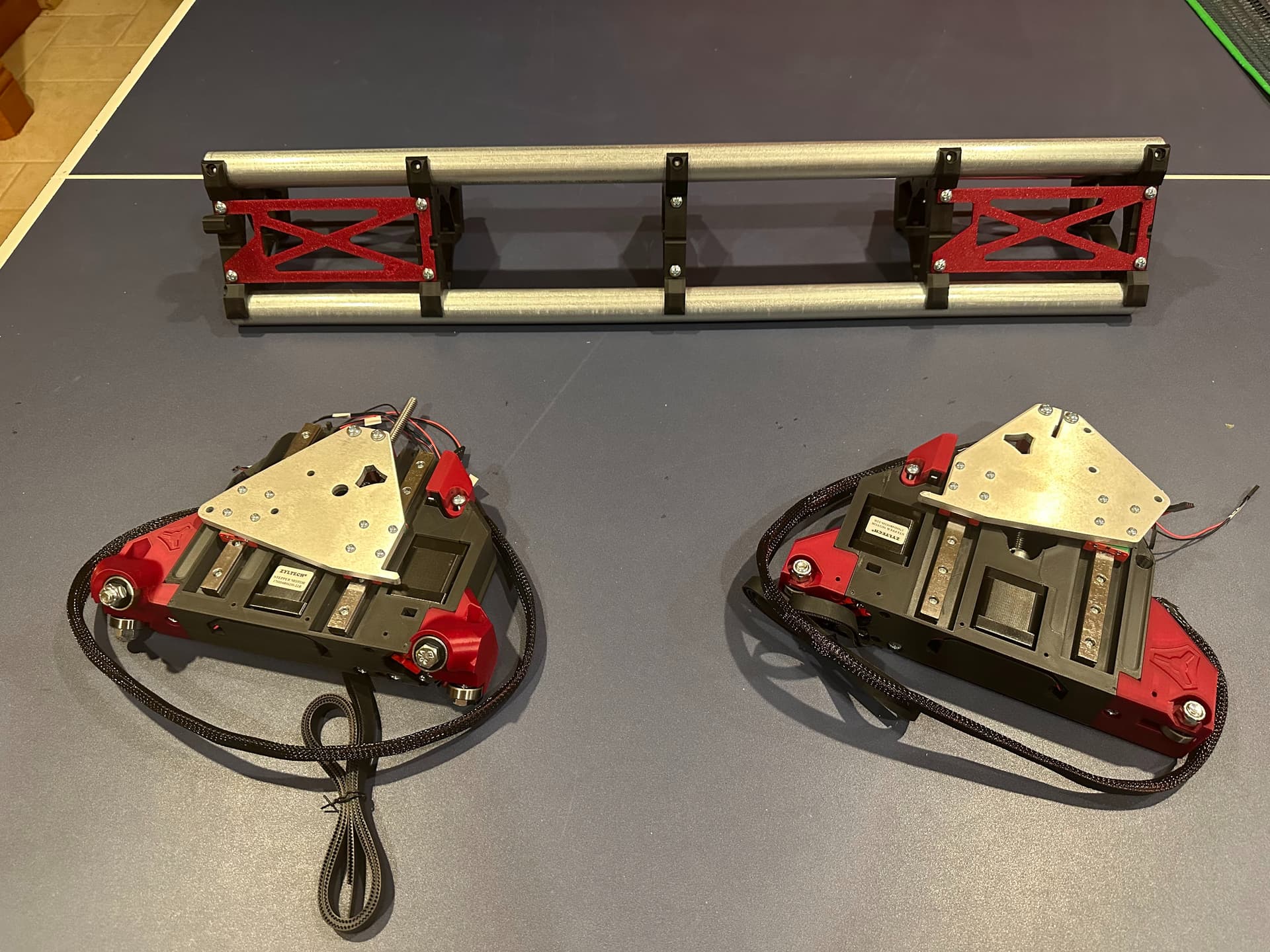
Parts are ready to assemble! I decided to build a 4ft x 2ft to start with and upgrade to a bigger one once I have some experience and start building the Koi filter, which needs bigger parts. Hmm that underused table tennis table sure would make a nice home for the LowRider…
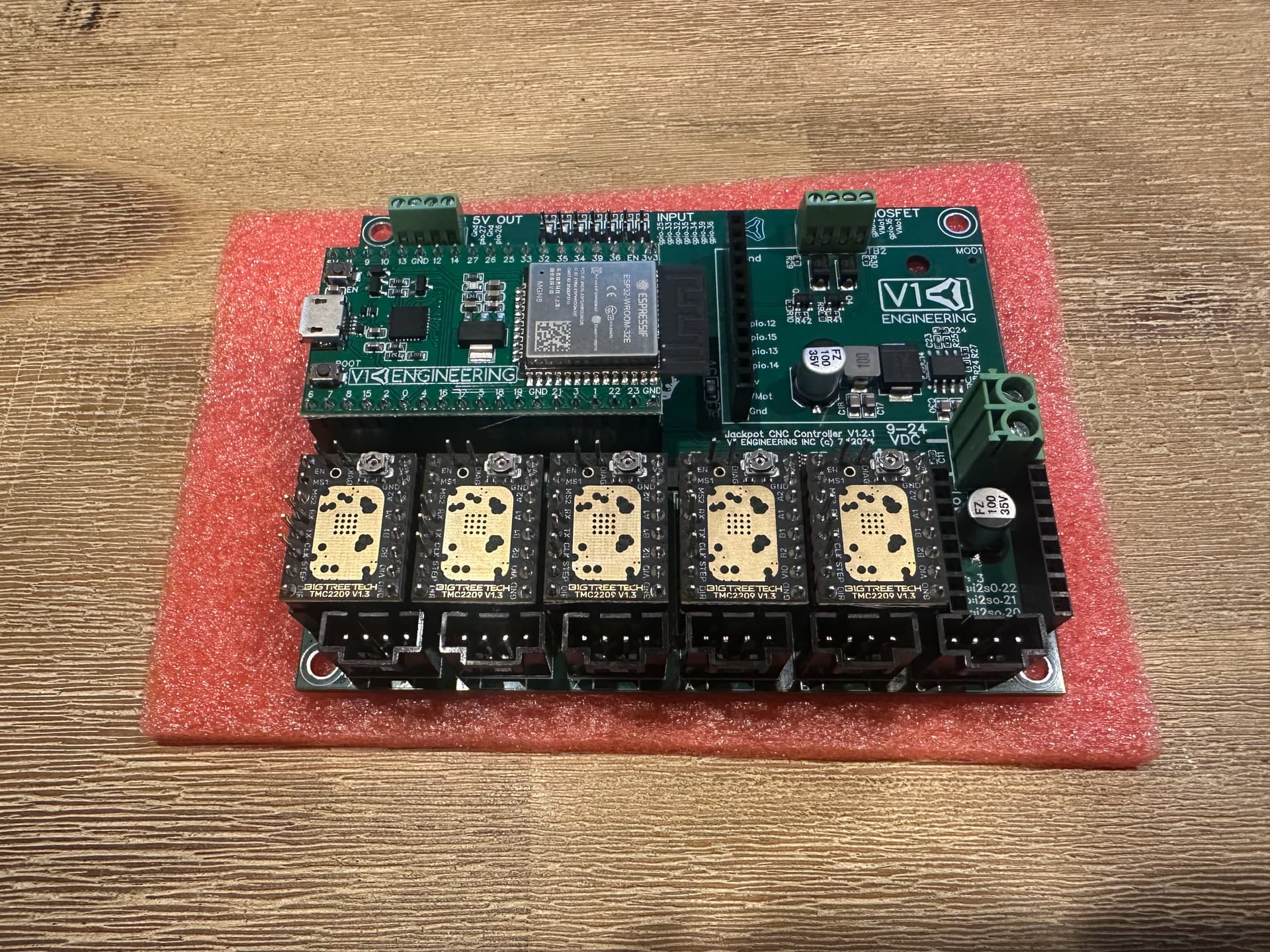
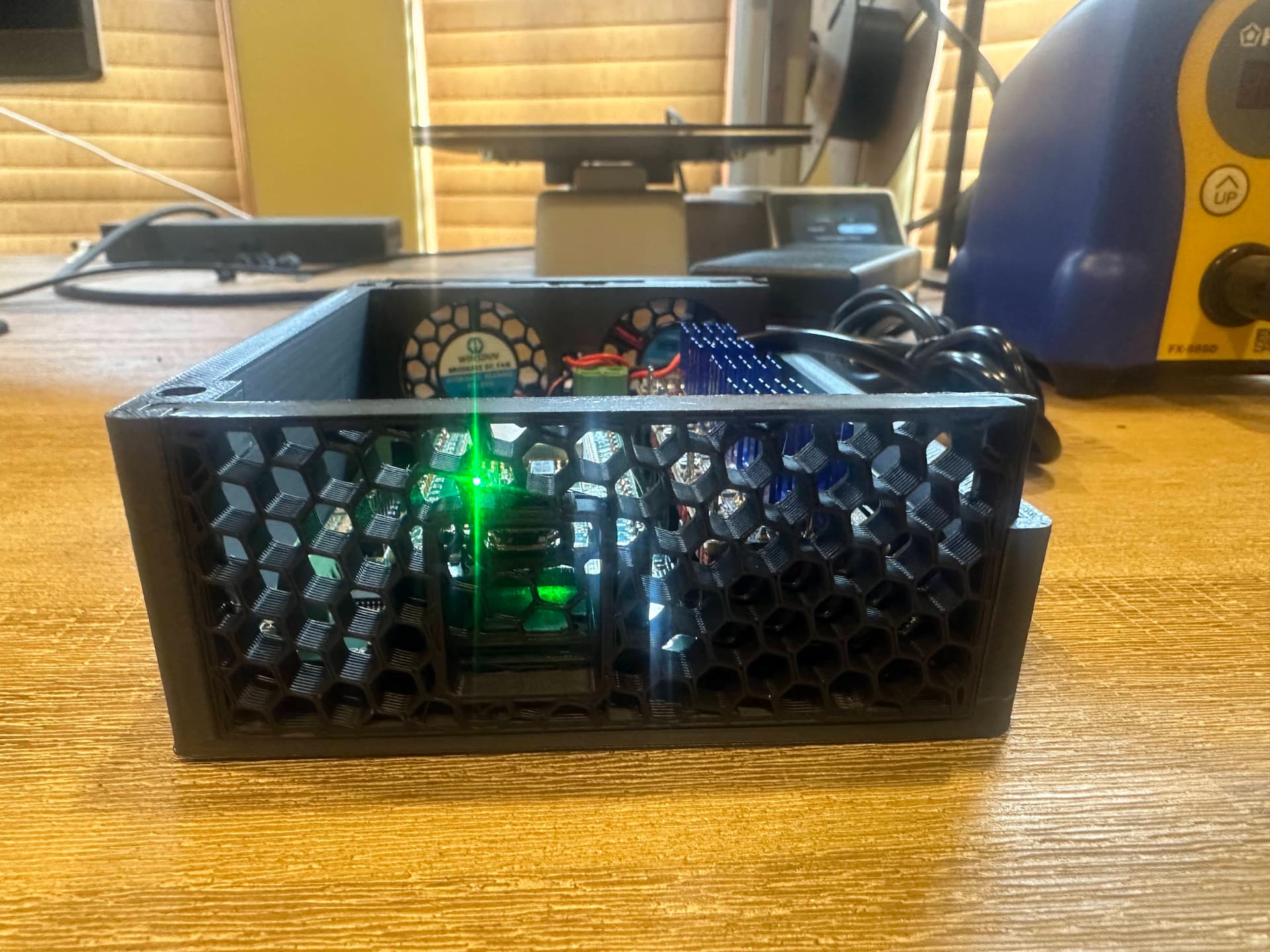
I bought the Jackpot controller, though I am thinking of building a custom box with a fan. The heatsinks for the stepper drivers had to be retrieved from the shipping carton in the trash because I thought they were missing at first.
What would the stack-up be if I wanted to prevent the table top getting damaged? Is it enough to have a 1/2 sheet of OSB, with 1/2" MDF rails on the side for the Y axis to run on, and 1/2 in spoil-board? Then position the router so the Z axis down limit cannot reach the OSB even if there is a z-axis crash. Are there any better choices for spoil-board than MDF? I really don’t like MDF because of the dust. I’m building the LowRider to cut plastic, and that’s going to mostly produce chips so most of the dust will come from the spoil-board.
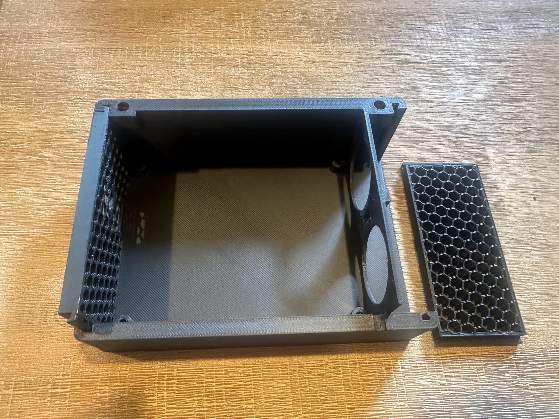
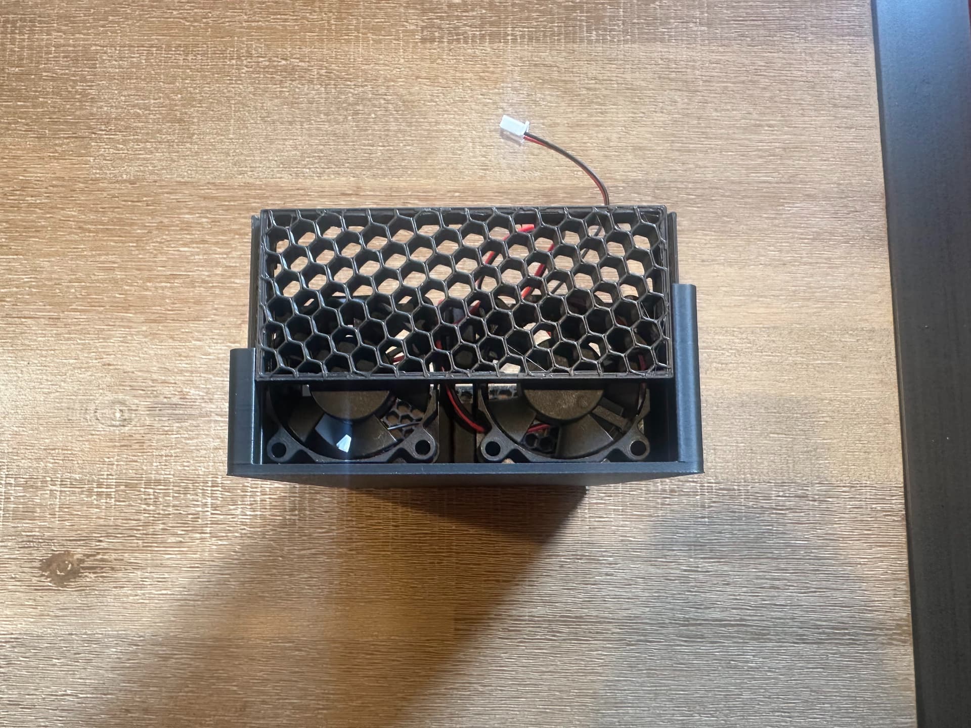
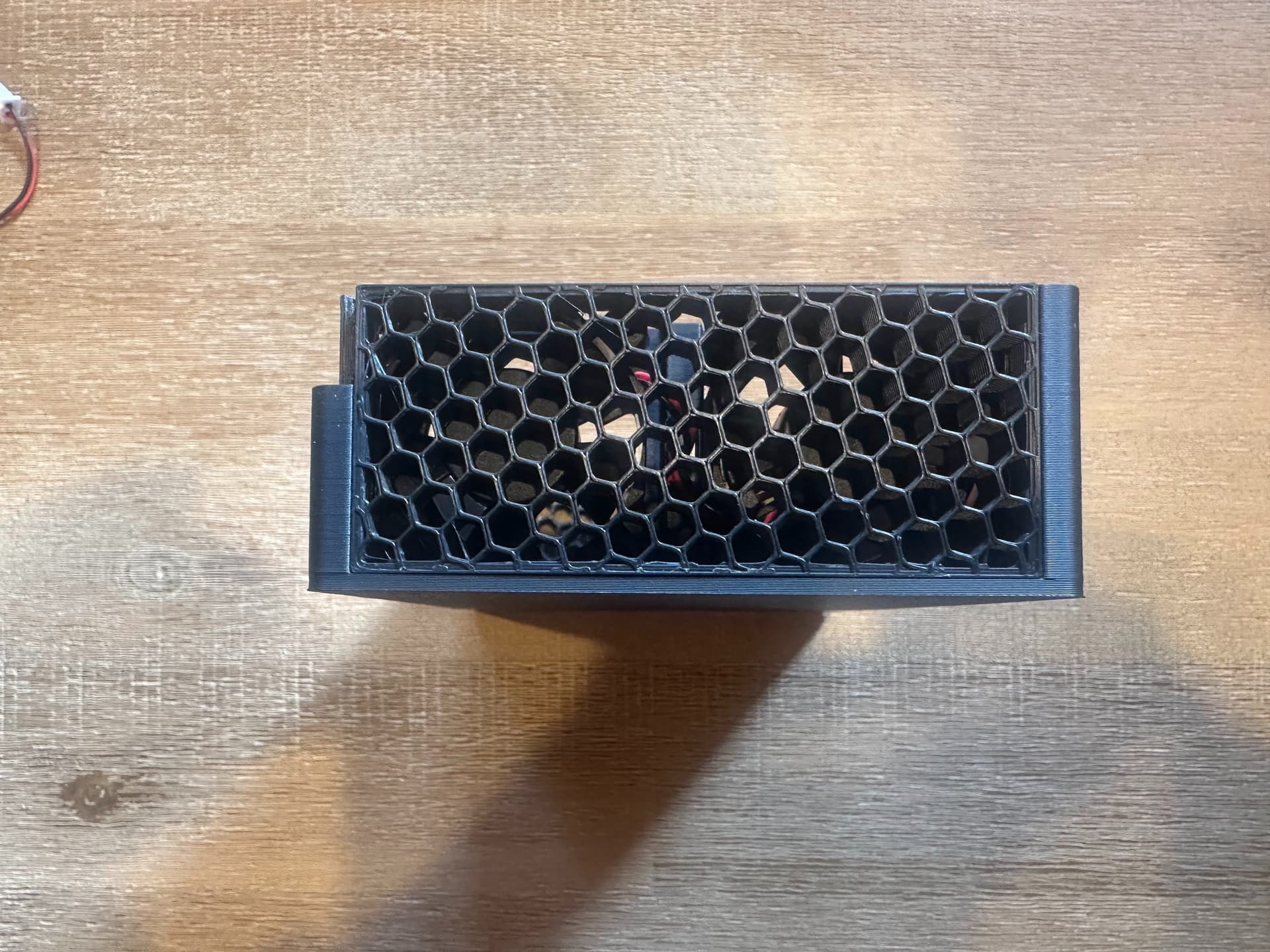
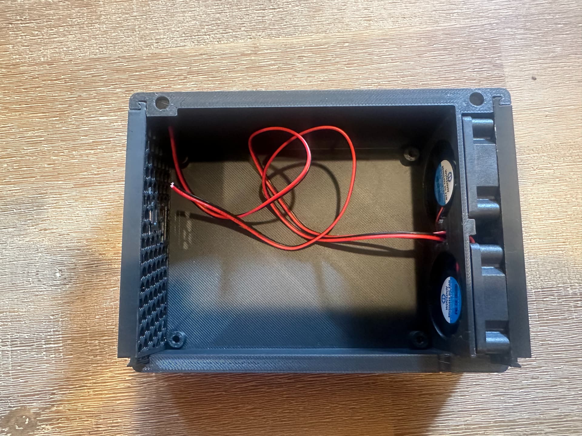
Bottom, front, back are printed as one piece. The left and right sides are printed flat on the plate with top and bottom surfaces removed to leave the infill pattern, which is “hexagon” at 15%. These are used for the vents. The parts slot together.
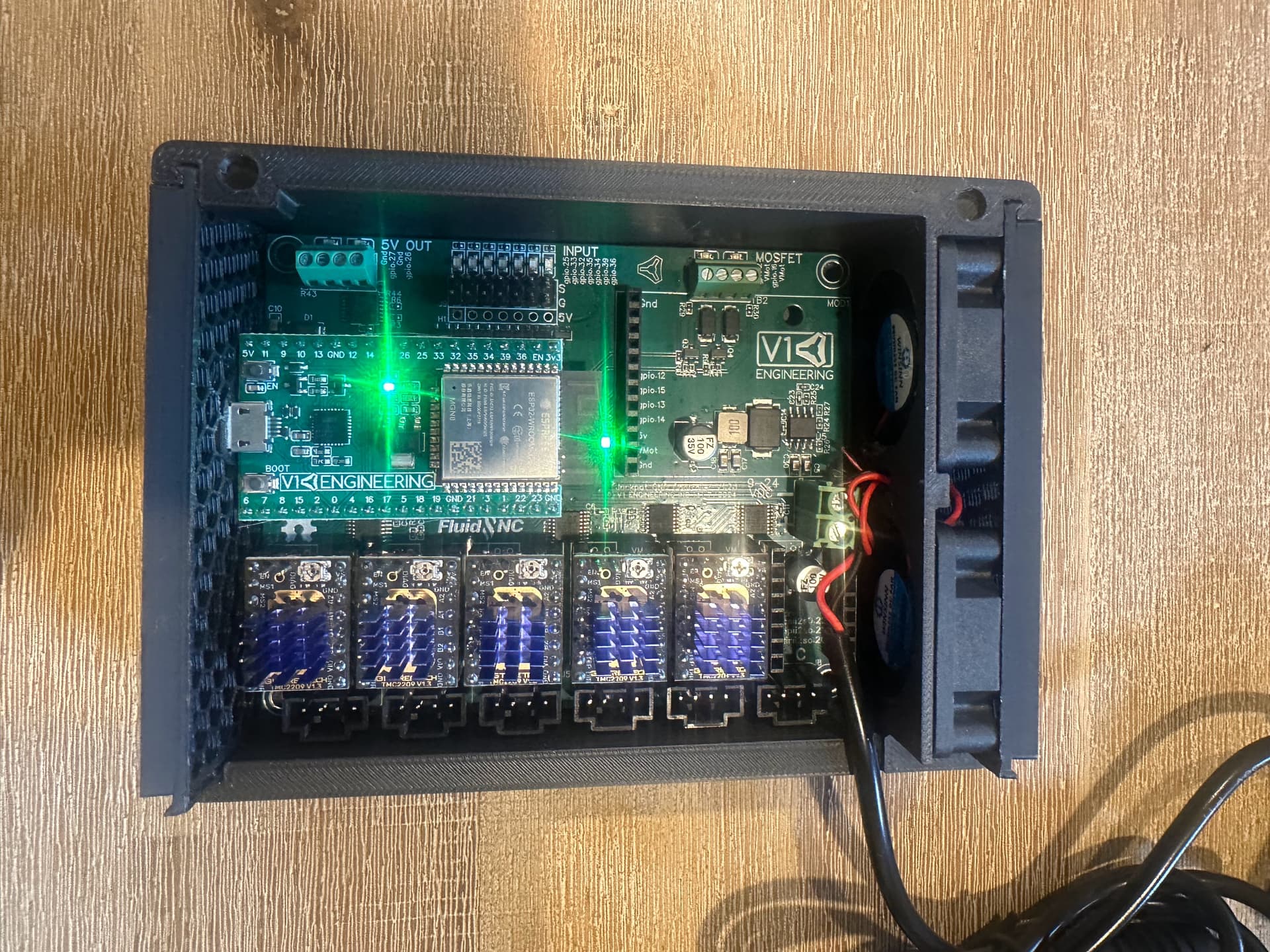
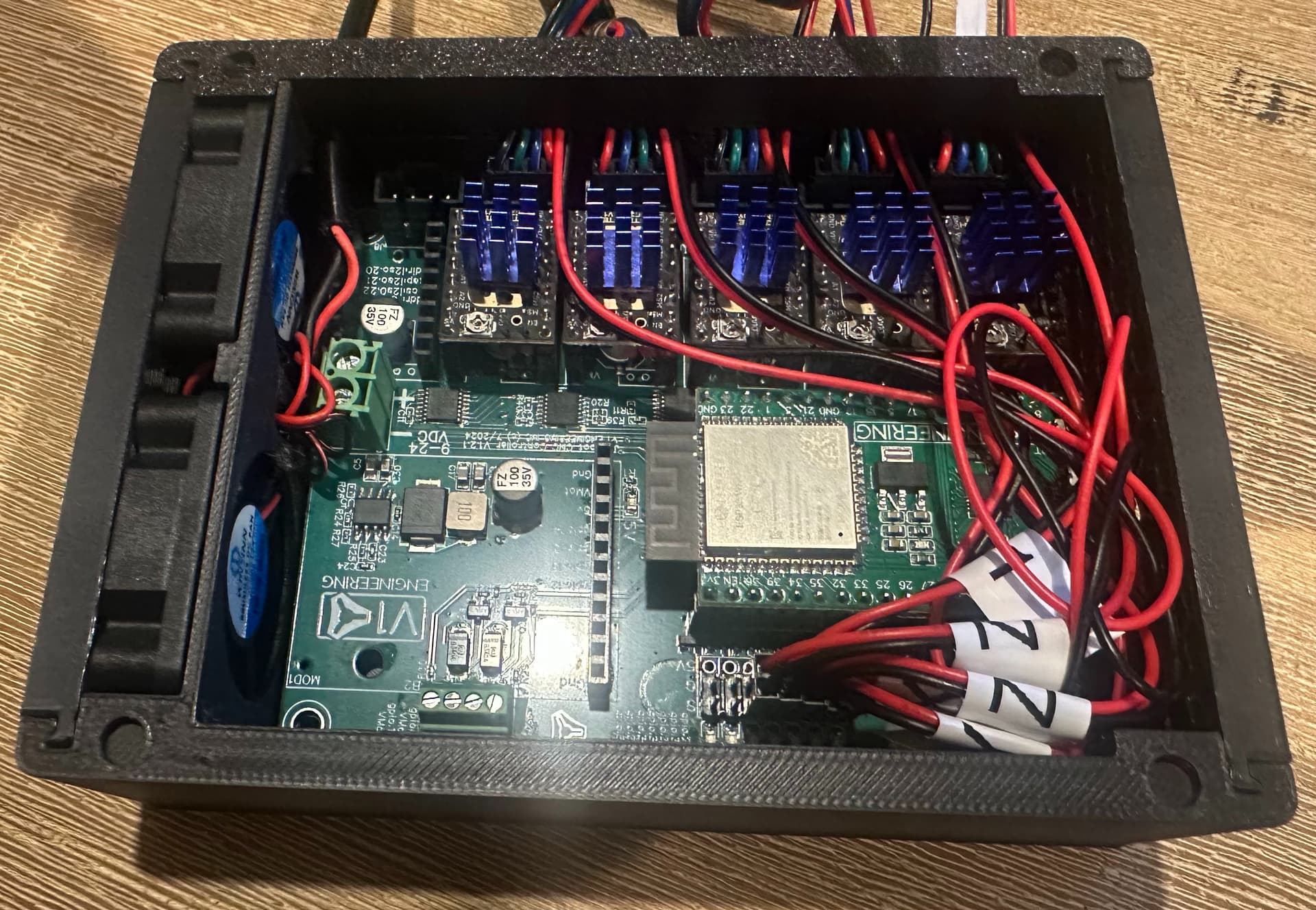
The Jackpot board is mounted inside. I should have brought the power cable in lower down so it could be run under the board. The fans are 24v and connected directly to power. The fans blow right to left across the board and warm air exits on the left.
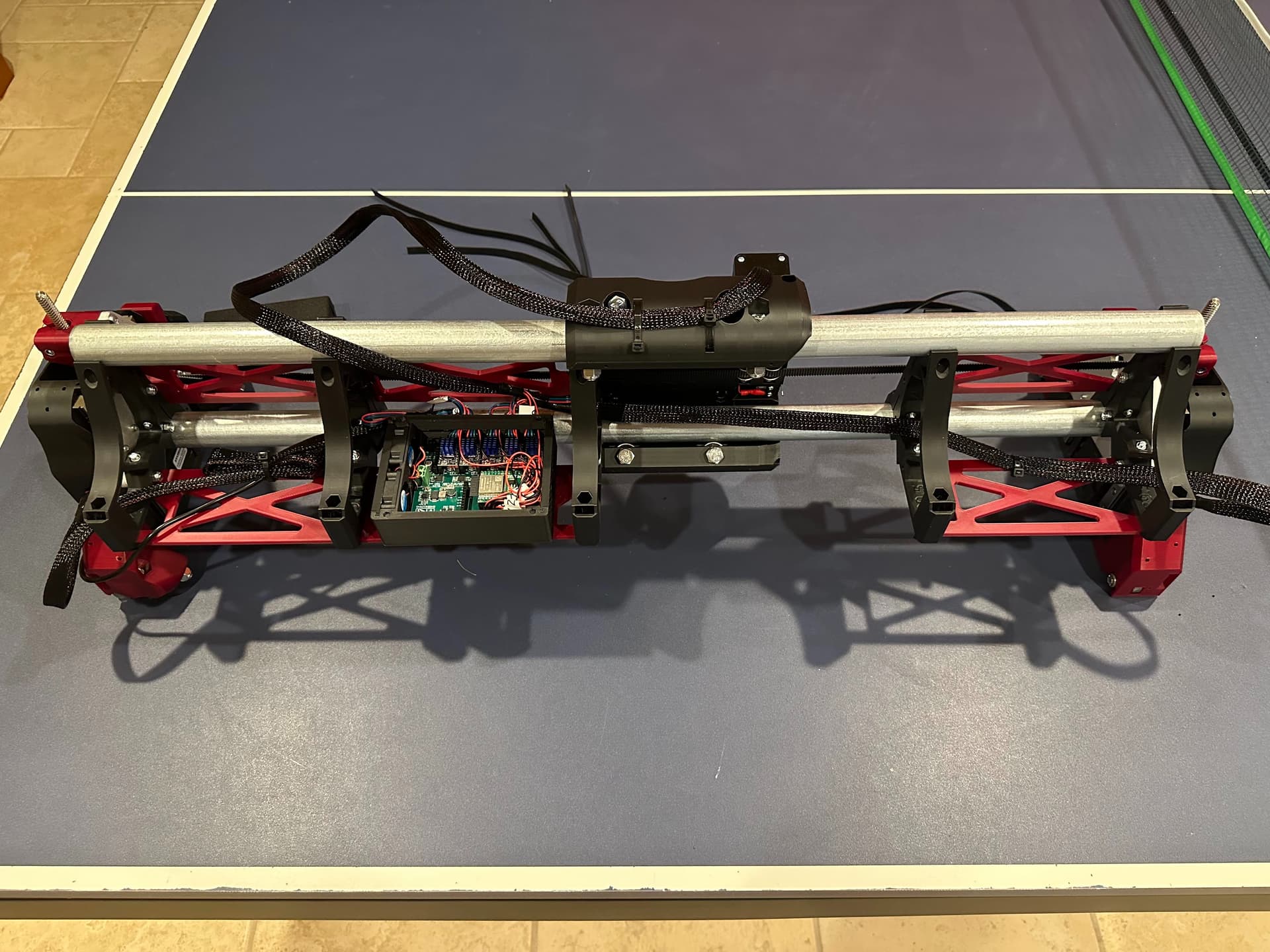
Fully assembled with the cables routed. The mess of cables to the right need to be tidied up a bit. The lid is supposed to be held by magnets in the 4 corners set into the 4 dimples, but they didn’t arrive yet.
Before installing the box to the gantry, I first tested everything to make sure all the steppers are moving in the right direction, and all switches are working. Getting FluidNC working was pretty straightforward. The most difficult thing was figuring out how to connect to my home network. I didn’t realize I had to use AP->STA mode at first, and ended up with Station mode, and then lost connection via my network. I had to access through the FluidNC Web Installer (via USB cable), which meant I had to add USB-serial driver to my A3 silicon Mac. In case anyone else needs this, there is a driver which must be installed from the App store and then Reboot the Mac.
Finally got everything working. IT MOVES!
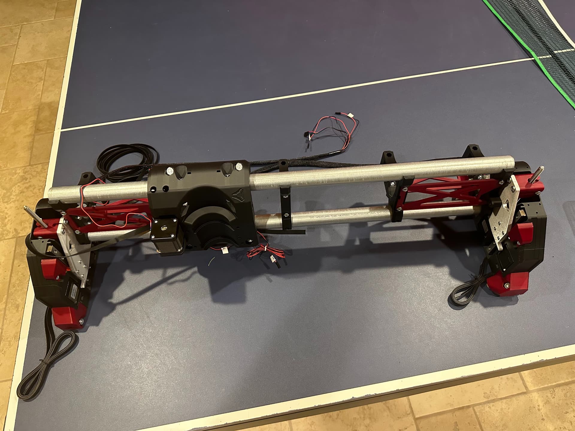
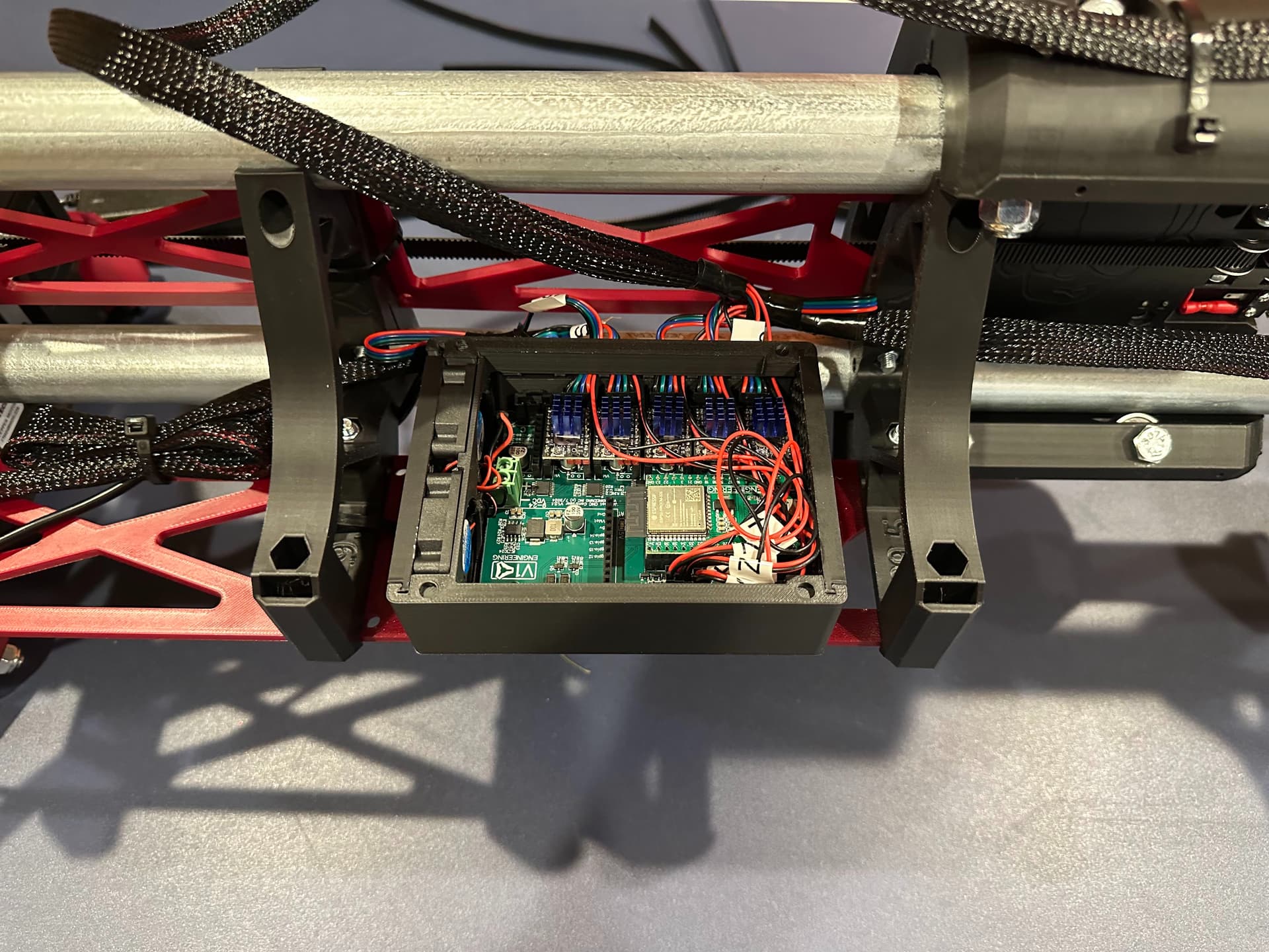
I added an extra set of struts to create a bay to hold the Jackpot box. The size makes it flush with the front of the brace, and there is enough space behind to route the cables.
At this point, everything is ready to go with Y-axis installation. Its Christmas Eve and the table tennis table is called upon to do its annual Christmas Party duty, so I need to pause here.
I was finally able to get back to this today. The LR4 is mounted to the table tennis table. Rail side is mounted on 4x1 MDF which is fastened to the table using masking-tape-and-super-glue fixture method. Its rock solid. The other side is just clamped for now. I had to reverse the Y direction to home correctly, which I did in the config file. Since I have a Mac, EstlCAM doesn’t work without emulation, so I made a test using the free version of Easel instead just to get things moving.
I don’t have the router or a pen mounted yet, but very happy to see that I can run gcode! There is a bit of squeaking / vibration from the z-axis when close to top of travel. Hoping that will go away after I level the z-axis.
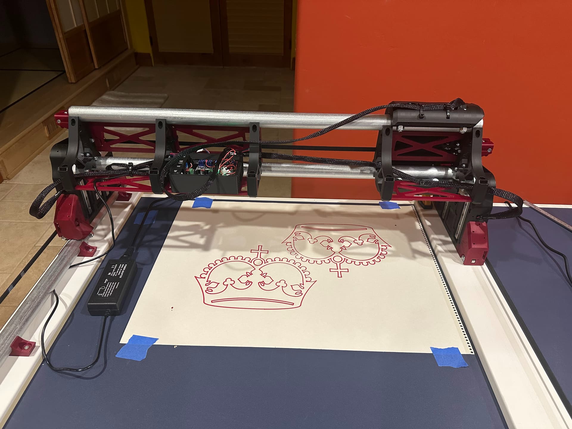
First & second test pattern with a pen. Leveling the z-axis was a bit tricky and I crashed the z-axis a few times. I still need to set the soft limits for all axis. Greasing the Z lead screw helped with the squeaking and vibration.