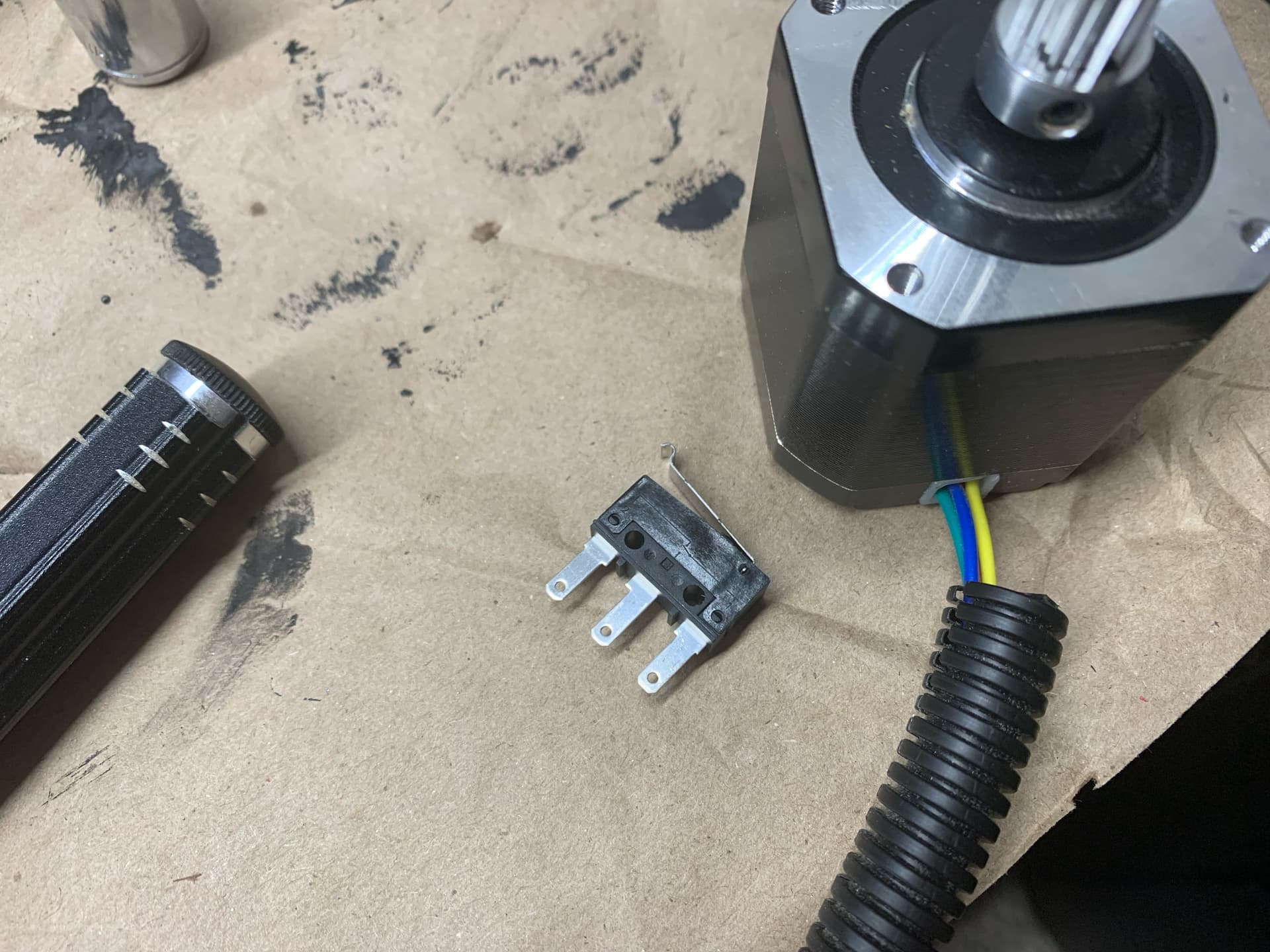
More likely Female Spade from that listing, with a better (or more thorough) insulating shroud. If you squint you can see that the middle contact in the end stop is a male spade style tipped mostly edge-on toward the camera.
2 Likes
You can get them at auto parts stores, in case you want to make sure you have the right size.
2 Likes
Couple more tidbits. The “spades” on mine are turned 90 degrees from the ones in the above photo. My end stop’s spades are 0.5mm thick x 2.8 mm wide. See pic:
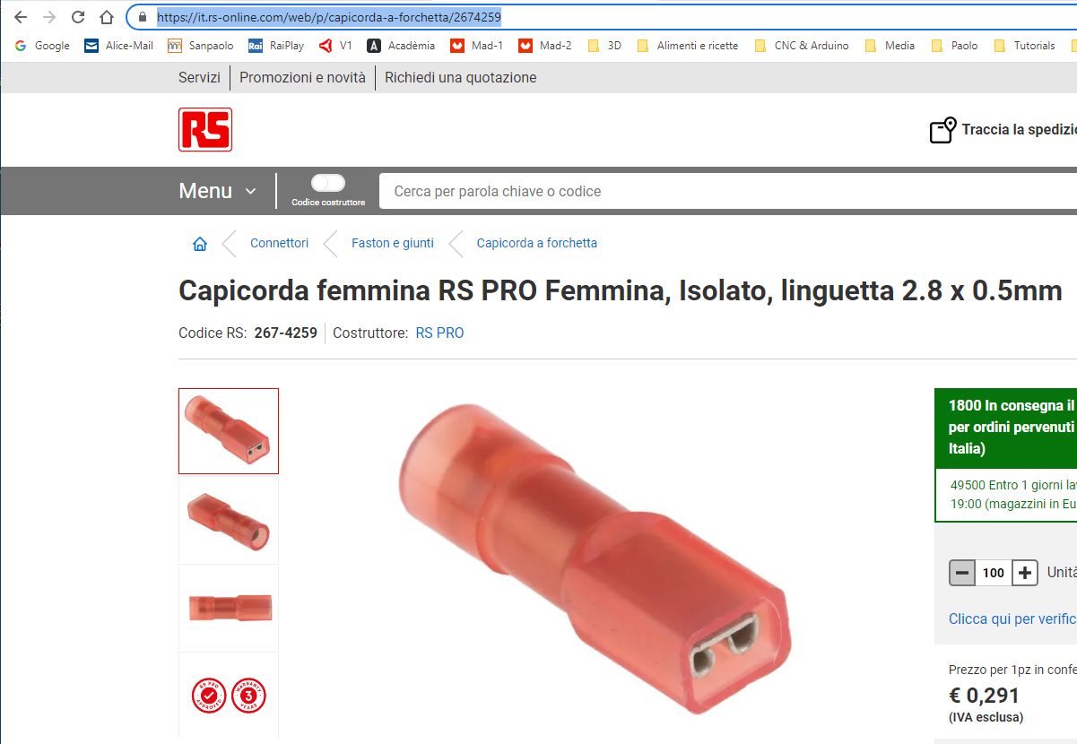
I don’t know if this can help you. In Italy we find these: https://it.rs-online.com/web/p/capicorda-a-forchetta/2674259
2 Likes
If you have the ability, I would solder them on (the smallest connection and stongest). If you want, these are the female spade connectors from that picture, https://amzn.to/3MWGgcO.
3 Likes
Possible typo. I could be mistaken, but I think the photo here:
.jpg)
… shows nuts in, bolt heads out.
Yet the page here:
https://docs.v1engineering.com/lowrider/#wheels
…says “Wheels installed, Heads in Nuts out.”
Am I looking at it wrong? Doesn’t the XZ plate face inward?
Another possible typo.
On this page:
https://docs.v1engineering.com/lowrider/#printed-parts
…the printed parts list says:
| 1 | Bearing Wheel Bracket Front | 30% | * See note below - Optional Version | Link |
|---|---|---|---|---|
| 1 | Bearing Wheel Bracket Rear | 30% | * See note below - Optional Version | Link |
…But wouldn’t there need to be 2 of each, instead of 1 of each? Two fronts, one for each side, and same for rear?
That is meant to be screw heads in on the wheel brackets.
No, I don’t think so. The bearing brackets you need one of each, for the wheel brackets you need 2 since they are the same. Still using a rail on the other side.
1 Like
Ah yes, no bearing wheels on the rail side. Duh.
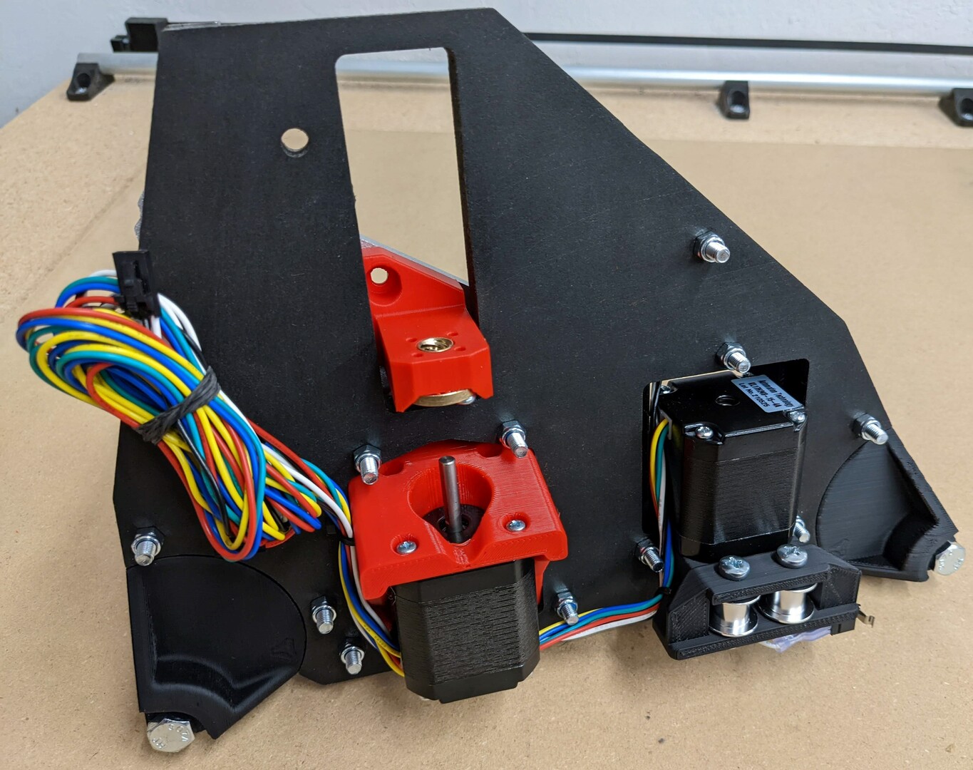
So just for clarity sake, these images are correct, that show the nuts on the same side as the XZ plate?
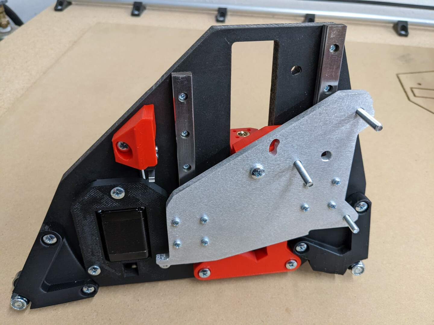
… And show the bolt heads on the same side as the stepper motors?
That seems to me like screw heads facing out, rather than in.
Sorry axle bolts, not the M5’s
I was focusing on the axle bolts. I’m still confused. The wording and the pics don’t seem to match. The side with the stepper motors showing I’m calling outside, and the side with the XZ plate, I’m calling inside. The pics show axle bolt heads facing out (if I am right on what is out), and nuts facing in. Yet if I am not mistaken, that is the opposite of the wording. I’m quite possibly wrong. Just trying to get clarity. 
Just like the picture shows. This statement “Wheels installed, Heads in Nuts out. Snug these four screws.” is referring to the M5 screws. Heads in towards the center, nuts out like all the rest. Would that be a better way to word it?
1 Like
Ah got it. I guess we were talking past each other.
Also, one idea/suggestion: See pic below for gist of it.
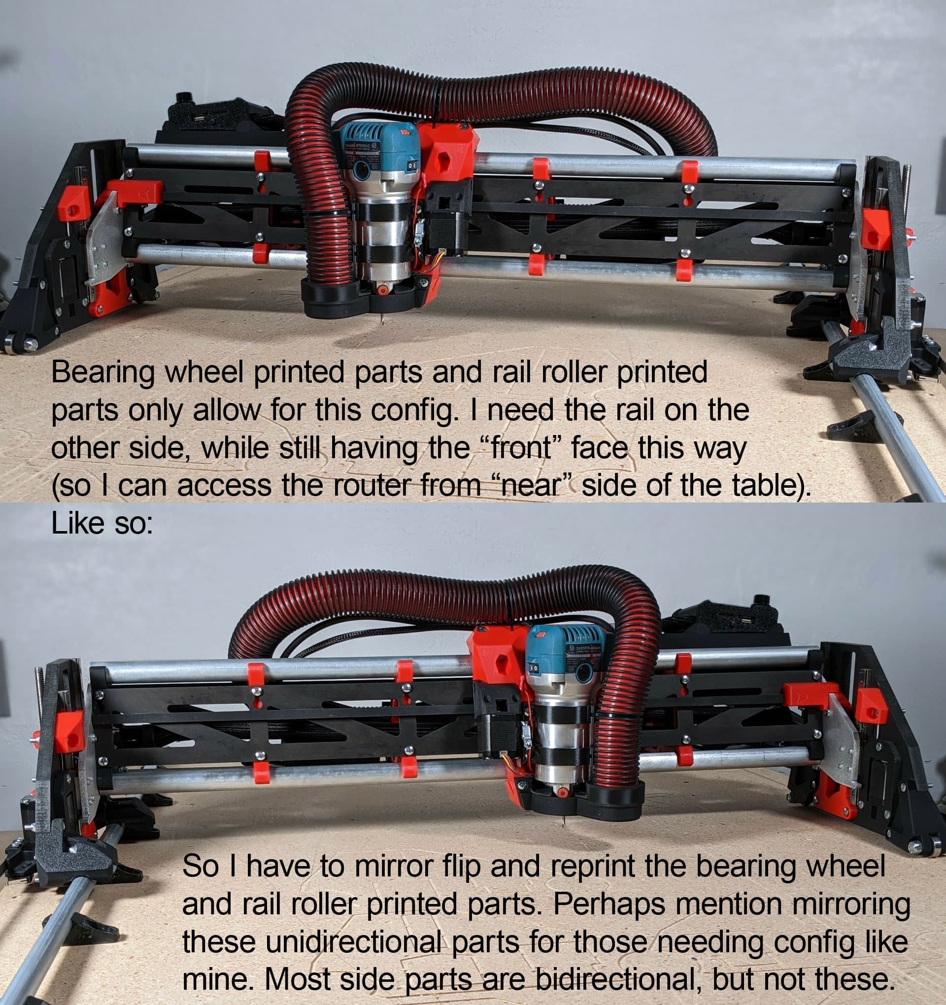
1 Like
I thought I had that listed somewhere near the parts list already. I will double check and add it if necessary.
I had 9 pages of notes, I could have missed it. I’ll check in a bit.
1 Like
This:
- Side Plates are done!
- Roll them around on your table making motor noises to make sure they work right.
… is hilarious!
From LowRider CNC V3 - V1 Engineering Documentation
…And this too:
- Best practice is to make robot noises while you move it up and down (feel free to tag me in your video when you do #V1LR3).
3 Likes
Culminating in:
- You nervous yet? It is time to fire it up! No need to make your own noises anymore it will do it for you. See I thought of everything.
From just before: LowRider CNC V3 - V1 Engineering Documentation
5 Likes