Thanks, you helped me a lot.
I will have to run a power cable to router and it will then have to run back and forth with xy gantry.
I am running a 24v 350w power supply which I have at half way point, and will run a cable chain setup for both x, and y with router power and board power, to fold over as it goes to rear along y, and lay down as it comes forward. Weird, I know, but that’s how I roll.
I hope it all works for you, it is looking good.
Table is not easy, mine is big for almost full sheet cuts, I can slide a full sheet on to the spoil board.
I don’t have the space for a full sheet table all the time - hoping to design something that can break down to store flat, and be setup quickly for either half sheet or full sheet.
I just realized, if you look above at @vicious1’s build from the tutorial, he’s doing similar - power supply inside, with the cord coming out the side. He would have to confirm how that works out for him.
That was really the only 24volt one at the time.
I was thinking it was going to draw more current with the 5 motors, drawing a max of 2 amps each. I
Know they probably won’t draw all at the same time, but if I am pushing it hard, I would rather have more than enough. Or have I calculated wrong? 24v x (5x2Amp)=240w.
Yes, I saw how it is run in the docs, I wasn’t sure if that was a big enough power supply, as I made a big machine, and wanted it to be good when running 24v, so that it did not run out of grunt, running just 12 volts.
Anyway, we are building with a great design, and setting up for the size of machine we want,
I think it will be great in the end, a bit of money spent on it, luckily I got bench wood free.
I have had fun building it, I hope my printed YZ plates stand up to the rest of the build.
That’s not really how you should be calculating power used by the stepper motors.
Each winding of the motor can take up to 2A max, but the driver itself is switching on and off like a buck converter to regulate that current. If your stepper has 2 ohms of phase resistance, it will have an average of 4V across it while it’s holding position. If you have a 24V supply then your stepper driver will be giving it 24V ~20% of the time and 0V ~80% of the time to average 4V out (really rough numbers because it gets complicated to do accurately). The stepper in question there would be using a max of 4W in each coil under that circumstance. I’m not actually sure if the stepper will ever see max current in both coils, but as a worst case you could probably assume so and say 8W per stepper.
That’s a really rough approximation, but should hopefully get you an idea of where to land, power supply wise. The 40W that Ryan suggest sounds logical, to me.
Thanks for that, all I did was a rough estimate of what I wanted to have power wise based on what would ever be a max. Required , but I knew it would be more than required.
Plenty of power available to run a spindle later on.
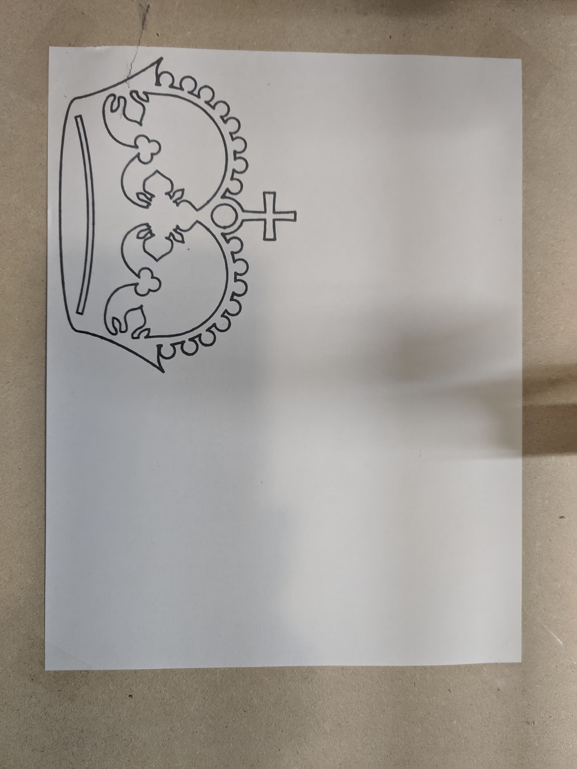
Got @DougJoseph’s toolless holder installed and sent the premade test crown gcode, However I think I have incorrect units, shouldn’t this take up a full 8.5"x11"?
Thanks! You can see where I tried to attach a pen before and it didn’t go well… The tool holder was the key that made it easy! I was able to Just snap it on once I was sure I wasn’t going to crash the gantry!
I may have to try a version of your “Large Crown”, I already have a roll of Kraft paper…
I’m starting to work on generating my GCODE. I’m using FreeCAD Path workbench with a Marlin Post Processor. My current struggle is mainly units - FreeCAD supports mm/min, but I can’t seem to find a way to add mm/s to it. The Marlin PostProcessor doesn’t change the speeds by default (Probably appropriate), so I get commands like this:
G1 X41.962 Y132.904 Z0.000 F43200.000
I would probably already be cutting if I ran etslCAM in wine, but I like to be stubborn! All in all, it’s come a long way since I last tried it a while ago, and luckily I was able to pull the CAM experience and dust off the 20+ years of cobwebs from Undergrad. I’m slowly moving along, I’ve figured out that this may be my “tinkering” project, much like others tinker with their 3D printers.
If I can figure out how to change my units (or give up and use a post step to convert speeds) I think I am prepared to start generating gcode and plotting/cutting my struts.
So far I haven’t had to break out the old textbook:
Ok, because I was comparing my Crown GCode to Ryans, and his was 720, so I was thinking that was mm/s. but it looks like it may have been my confusion from the Estlcam documentation. So maybe I am almost ready for cuts?
Ok, after quite a bit of time away (I’m not sure how a “quick distraction” took so long…), I’m back for my table build. I realize that after all this time, I’m definitely going to have to take care of my grub screws. They got loose!