Lowrider 2 - Z axis losing steps

Good morning,

Finishing an LR2 build that I’ve had around for ages (lack of time). Build is complete, but I’m encountering an issue

If I drill one area without raising the toolhead, all is fine. But on the second area where the tool head need to be raised to reach it, it actually drags on wood, and the resulting cut is deeper. It seems it’s losing steps when raising.

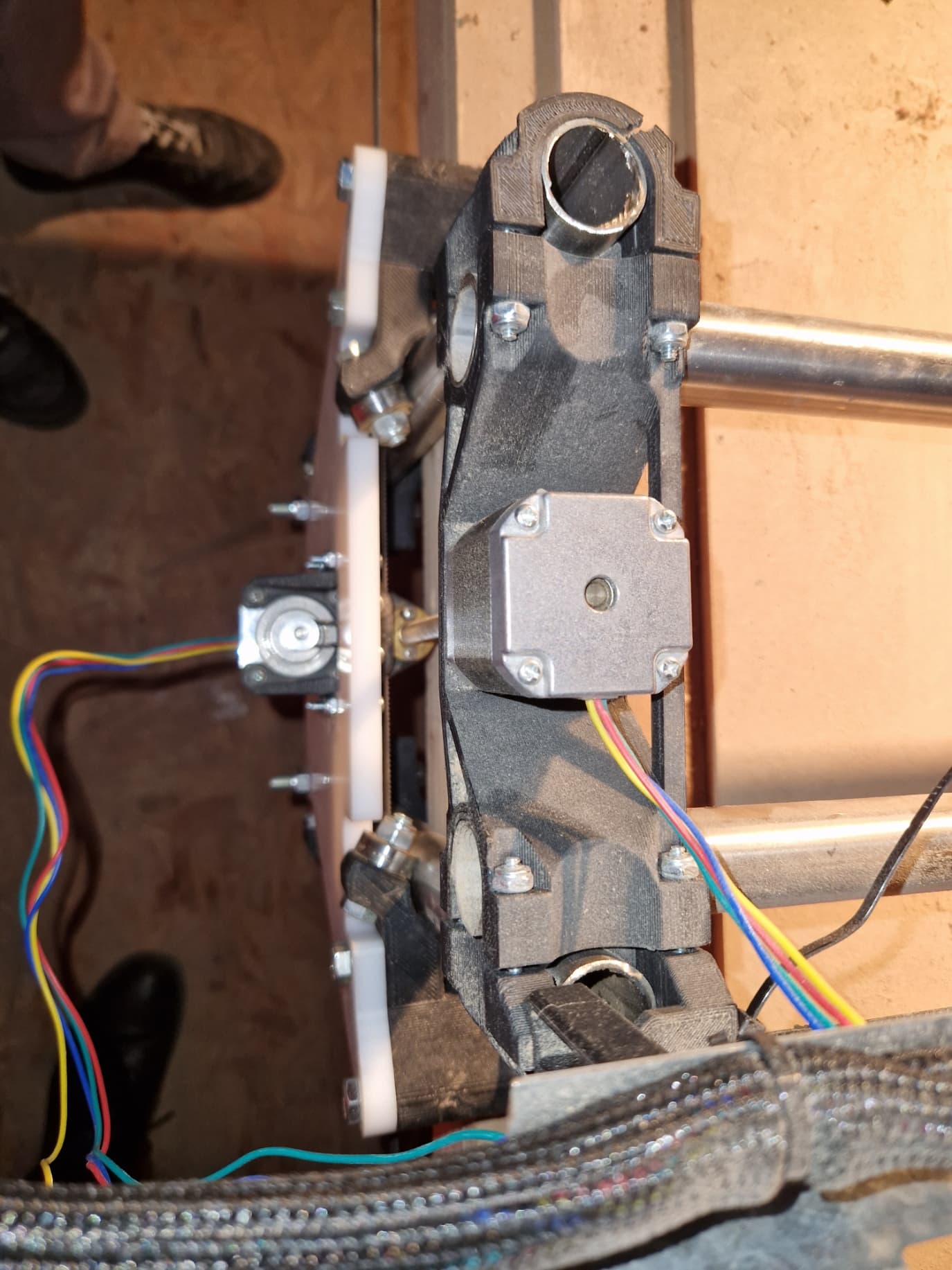
We confirmed this by removing the spindle, and simply adding a little bit of pressure on the stepper motor, we could hear the stepper motor losing steps.

Reading through some material on this forum, I’ve found to leads to investigate:

1/ Check VREF level
2/ check Z connector for second stepper motor and ensure it’s using a dedicated mosfet

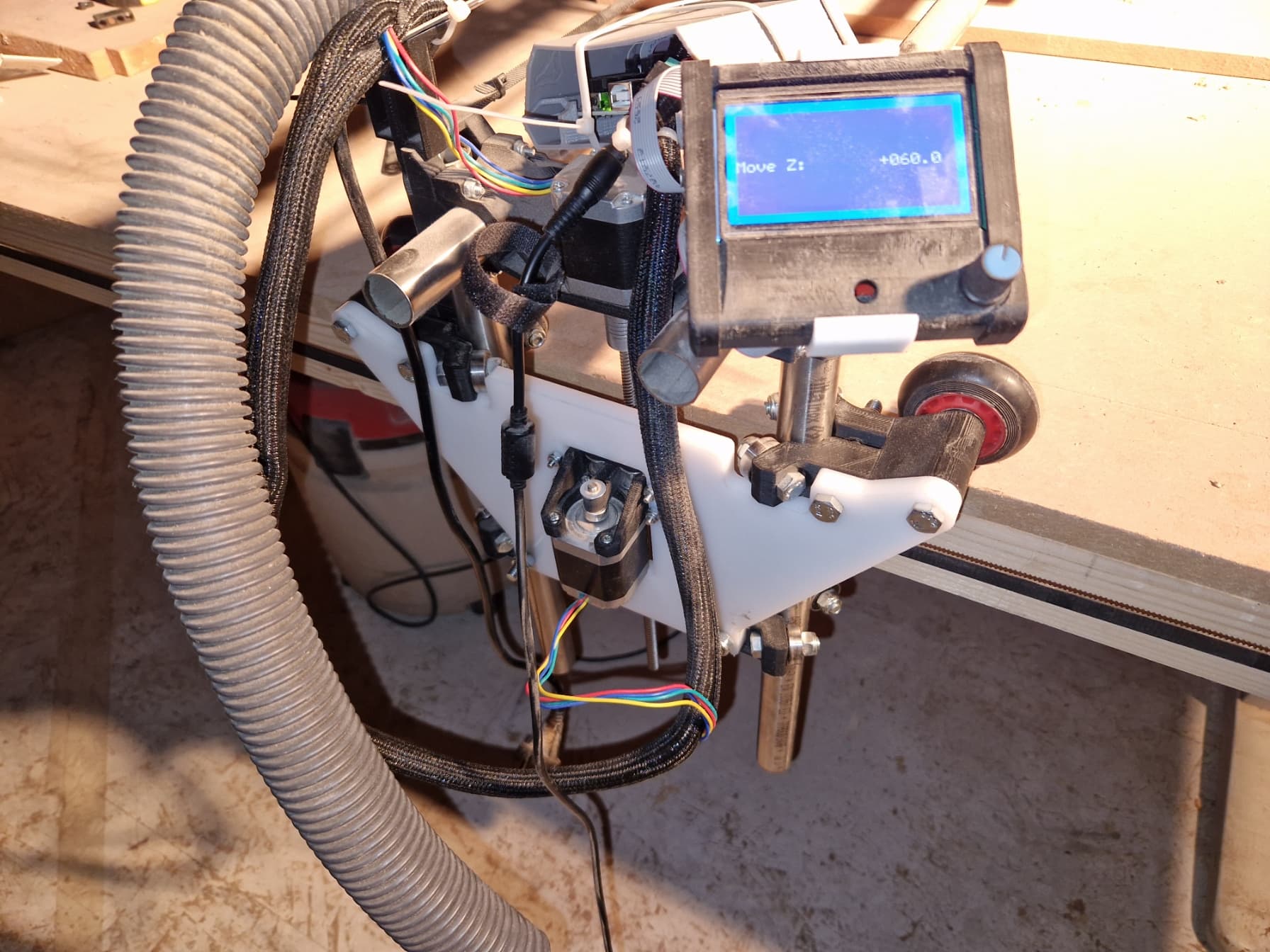
the control board is a mini Rambo, and there start my problems…

On 1/, I could not find material on the Internet that would allow me to adjust Vref. Looks like mini Rambo control the stepper motor current using a PWM, and it’s defined by SW when compiling Marlin. Not exactly practical for trial and error, unless I missed something ?

On 2/ Indeed, I’m using both Z connector. The connector next to it is free (E0), but I’m unsure if the default firmware will use it to control the second stepper motor. I’m using V1 engineering mini Rambo firmware, no change

I tried to look in the firmware source code, but i’m not too familiar with Marlin config option, and could not find where dual stepper motor driver could be defined

To note:

  • we use Fusion360 with the post processor, and don’t touch the G-Code
  • We checked the coupling, tightened the coupler screws, and added grease to the leadscrew
  • When drilling the first pocket, depth is constant, it’s when raising that it fails to raise all the way

See picture of three consequent areas drilled during the same phase, first area is fine, second area is deeper than what it should be, third area is even deeper (from bottom to top)

Any advice would be appreciated

Regards

Using the 2 Z connections the way you are is splitting the current between the 2 motors, resulting in much less available torque. You’ll need to reduce the Z max velocity and acceleration or move the second Z motor to the E0 connection. I don’t run a Rambo (or mini Rambo) myself, but I think if you’re using the Dual Endstop version of the firmware it should be set to use the other stepper driver for the second Z motor by default.

I’m not exactly sure how you have this board wired up. There are two stepper motors on the Y and the Z axes, and I don’t believe E0 is set up for the second Y stepper motor. The Mini Rambo board only has 4 drivers, so Ryan spec’ed the wiring to be serial/series for the X and the Z stepper motors. You will find the wiring diagram for serial/series wiring under the “Archive” link at the bottom of this page.

Ryan no longer sells the Mini Rambo nor the series/serial cable. If you purchased your system from Ryan, you should have received the serial/series wiring harness for the Z motors. I had an idea based on a post on the forum. If I was going to make a series/serial wiring harness, I would start by purchasing a set of these. I would then cut the traces on this board and wire jumpers to make this a serial/series connection. This keeps the wiring clean, plus it makes it simple to upgrade the system to a five-driver control board in the future.

As for adjusting the current, you will need to recompile the firmware. For Windows, PlatformIO is the recommended software for recompiling and flashing the firmware for the Mini Rambo board. You will find the source for the firmware on this page, and you want the V1CNC_MiniRambo version. The current is set in this line in configuration_adv.h:

#define PWM_MOTOR_CURRENT { 850, 850, 850 } // { 1300, 1300, 1250 }          // Values in milliamps

The Mini Rambo uses A4982 stepper drivers with a max current of 2A. What I don’t know is whether the current settings in PWM_MOTOR_CURRENT are Max or RMS. Regardless, I would increase the current with caution, and pay attention to the temperature of the stepper motors. Given the PLA used for the brackets, it is possible to run the steppers hot enough to melt the PLA. Note that you should not need to adjust the current if you use serial/series wiring.

If you are using serial/series wiring, there is some benefit to running your control board at 24V, though there are many builds that just used 12V.

1 Like

Thanks for this information

I stand corrected, I checked the wiring, and they are indeed in series.

The mini Rambo is powered through a 12V power supply. I’ll try a 24V power supply.
I’ll also try increasing PWM_MOTOR_CURRENT values (I assume I only need to change the Z axis).

Increasing to 24V will only help with rapid movements. It will have no impact on normal (cutting) movements. Series wiring reduces the torque for rapid movements, and going to 24V can help if that is where you are losing steps.

There are a lot of successful LR2 builds at 12V and default current settings. I suggest you check for some sort of mechanical issue…lead screw bent or misaligned, screws need to be lubed, grub screws on the connector loose, etc.

Well, we checked everything, and it’s clearly mechanical

It seems the Y-plate (built using 12mm MDF) is flexing during movement, causing a lead screw alignement. Not sure if it’s the quality of the MDF material used, or something else.

We’ll continue to look at mechanics while getting Y-plate in an alternate material

It’s a pretty common recommendation to allow a little wiggle in the mounting of the lead screw nuts to the structure. You don’t want up-and-down slop, but if the nuts can self-align when the leadscrew itself is moving a bit due to flex elsewhere in the machine, that might help alleviate the symptoms you’re seeing.

We changed the material as a friend was able to machine cut out of PE HD the mounting plate, see picture:

However, we still get a little bit of flex on one of the plate, see picture below:

If the assembly screws for the wheels and the tubing are tight, we can see that a small pressure on the top of one of the stepper motor when it’s moving up will result into the motor losing a step. If we give a little bit of wiggle movement (meaning all mounting screws used for the wheels support and the tubing alignement support are very slightly loose), this reduces flex and require a much higher force for the stepper motor to lose a step

So questions / considerations:

  • Based on the way the stepper motor are being mounted, it does not seem that very tight mounting of the wheels support is required to ensure accuracy
  • It looks to us the flex is caused by printing tolerance on the mounting structure of the vertical tubes, is this correct ?
  • Could we correct the spacing by modifying one of the mounting piece (I can’t describe it verbally, this is the piece that essentially allows to assemble the vertical tube with the horizontal tube), does this even make sense ?

Thanks !

Have you checked the dimensions between the bolts on the plate? If they are too far apart (or the printed XZ part is too small), then it will want to bend like that.

You could maybe cad up a larger spacer inside the right angle joints of the XZ part.

Does the flex relax if you slightly loosen the tube holding? Can you add some angle to the plate to keep it more flat?

I’ll have to take a measurement, but this was a cut based on the DXF. And it was identical in dimension to the MDF version I had done earlier (ie wood) at another company.

Indeed, it does look like there is a dimensional tolerance at play.

The flex does relax if we loosen the tube holding (that’s the first thing we tried). As to add an angle, that’s an option. But I’ll go first with a spacer in the XZ part holding the vertical and horizontal tube together.

I can whip up a new version of the file, but if anyone has the parametric version of the J_spacer.stl file (Fusion would be perfect), that would be appreciated.

So we took measurements at various locations, and this is very puzzling

Both plates are identical

Measurements are taken just below the X “holder” where the junction of the horizontal tubes and vertical tubes take place - see attached picture (top in the list below), just below the lower piece with the bearing (middle). We measure the distance from outer dimension to outer dimension of the tubes

Here’s what we have:

On the side where there is very little warping:
Top : 198.95mm
Middle: 201.83

On the side where’s there’s warping:
Top: 197.98
Middle: 195.11

The measure at the top is probably the most accurate, since it’s only driven by the X mounting mechanical parts
The middle measurement is either measurement error, or is caused by the tube being misaligned. What is odd is that if the top measurement is smaller, I would have expected the distance to increase, not decrease

Anyway, here are some questions:

  • What are the parts that change between metric (25mm tube) and imperial (25.54mm). I originally ordered the full kit to V1 engineering, but there might have been a metric / imperial part mix up that would explain the 1mm error at the top
  • What is the target dimension, 25mm OD tube to 25mm OD tube ? Or any reference dimension that I could use to adjust the mechanics ?

From this diagram in the schematics, I would expect 8,6,5 and 7 to be designed according to tubing dimension, am I correct ?

Thanks

So as an update: we quickly redesigned part number 6, with allowed us to adjust the distance between the two vertical tubes. And voilà, using a 2mm version (ie one which adds 2mm), we were able to have a consistent distance between the tubes, with no flexing of the plate.

Coincidentally, part number 8 had originally cracked, we assume because of this mechanical constraint which was causing the XY plate to flex. Hopefully with this small change, this will work better