I like the look of that. Those trusses are a shape that often looks like it belongs.
1 Like
Nice!
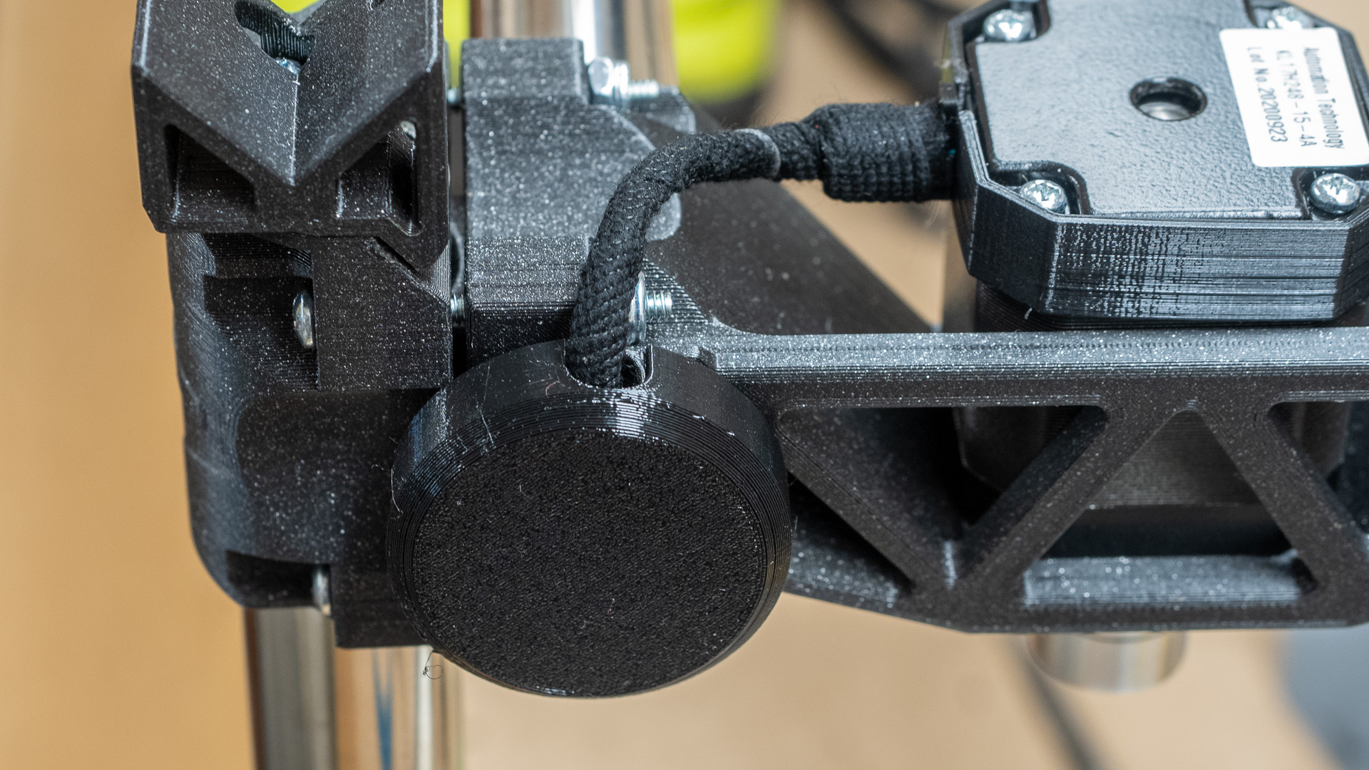
1 Like
I’m not sure just how free the centre assembly has to be - it runs very smoothly but it needs light pressure to move it - a gentle flick will move it a foot or two, not send it flying out of control. I’ve used every trick I know to align the brackets, if the consensus is that they need to be really free, I can drill the mounting holes a little more oversize and slightly spread the foot of each x roller before tightening it.
Perhaps it’s something that a little weight will improve?
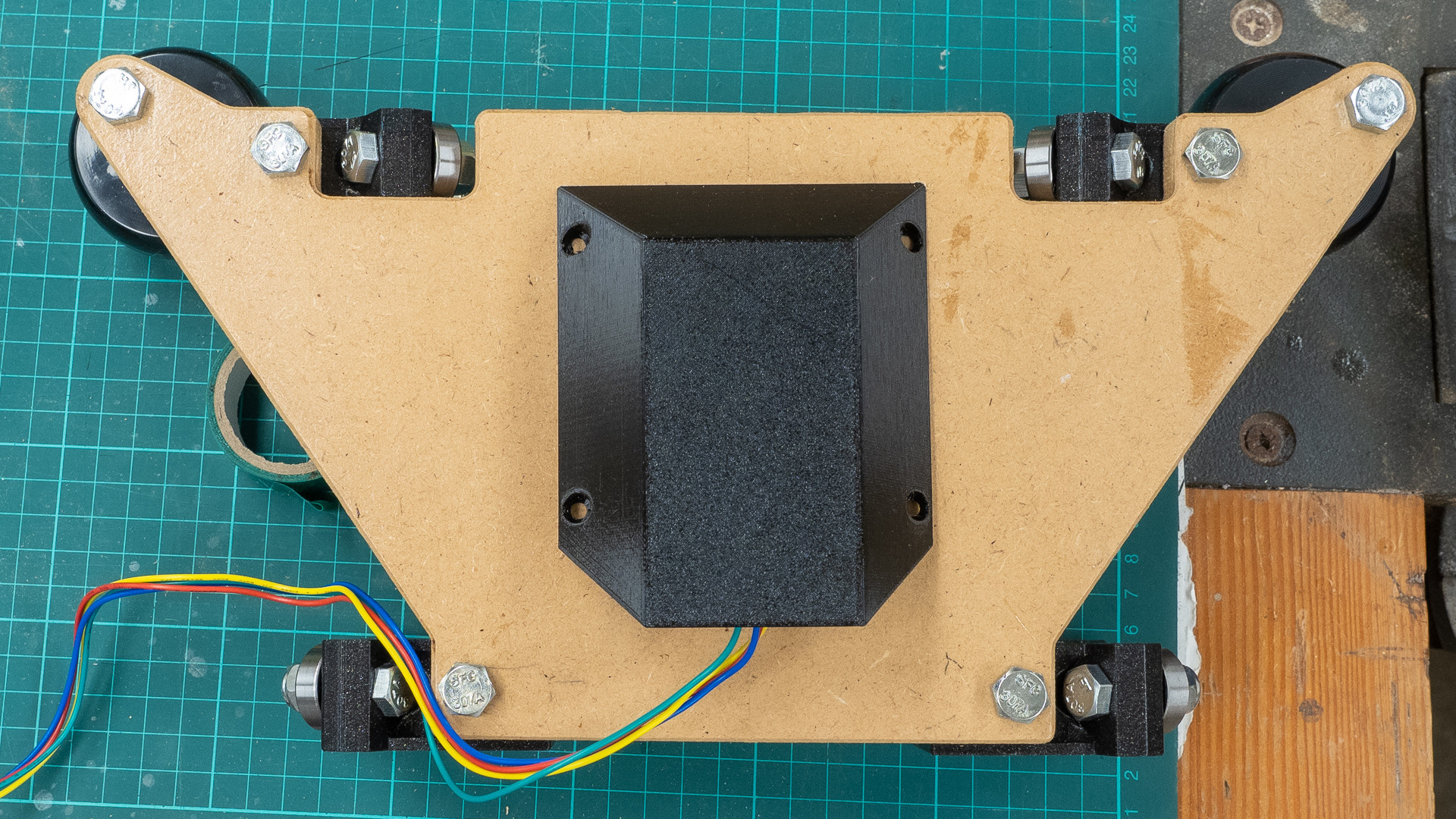
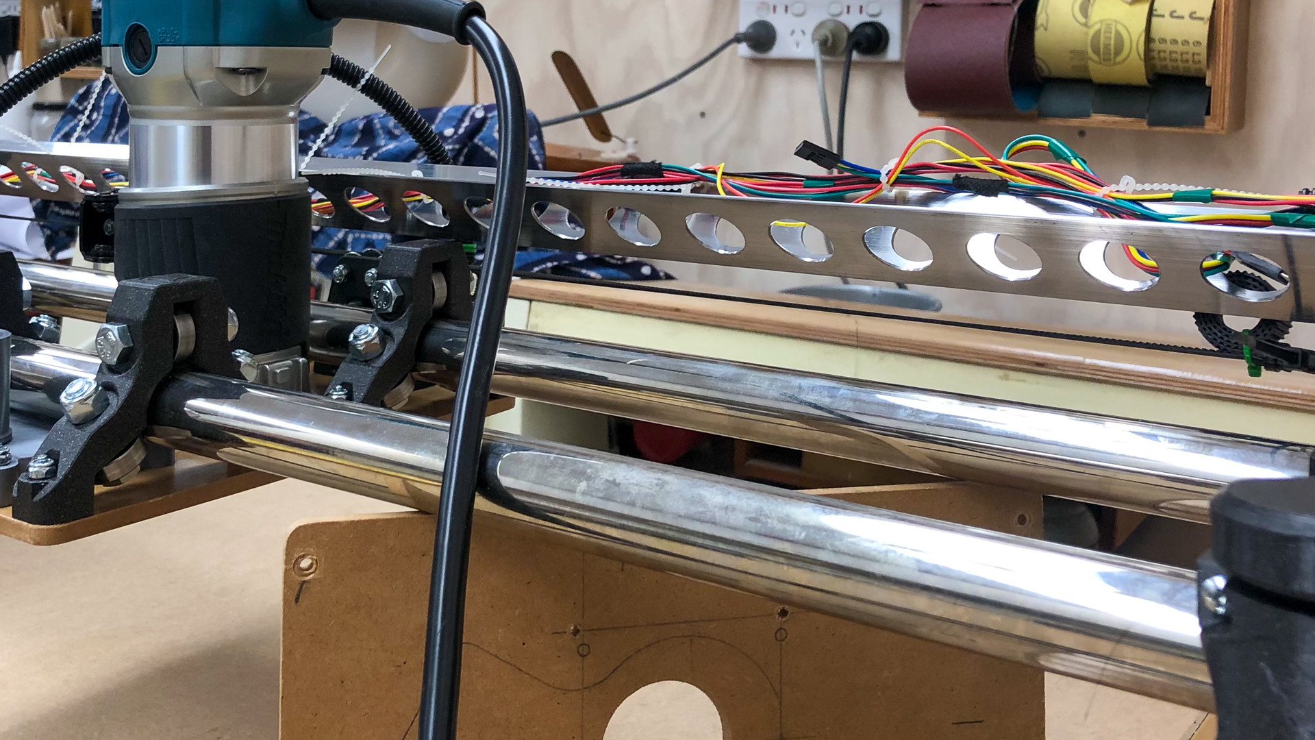
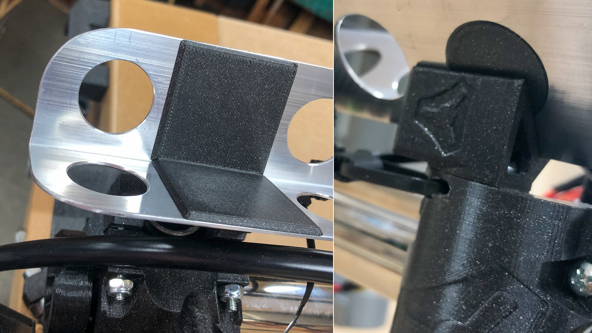
On another note - inspired by the Gnarly case, I thought I’d pop out a cover for the stepper. As much as I like the shape of the plate, I’ve never been in love with the exposed belt. Too much do you think? I can shrink it quite a bit in the final version.
It should keep little fingers fingers out, not that they’ll be there when it’s running. No it’s not square, but it will be - just waiting for some printing supplies to arrive from the other side of the world.
2 Likes
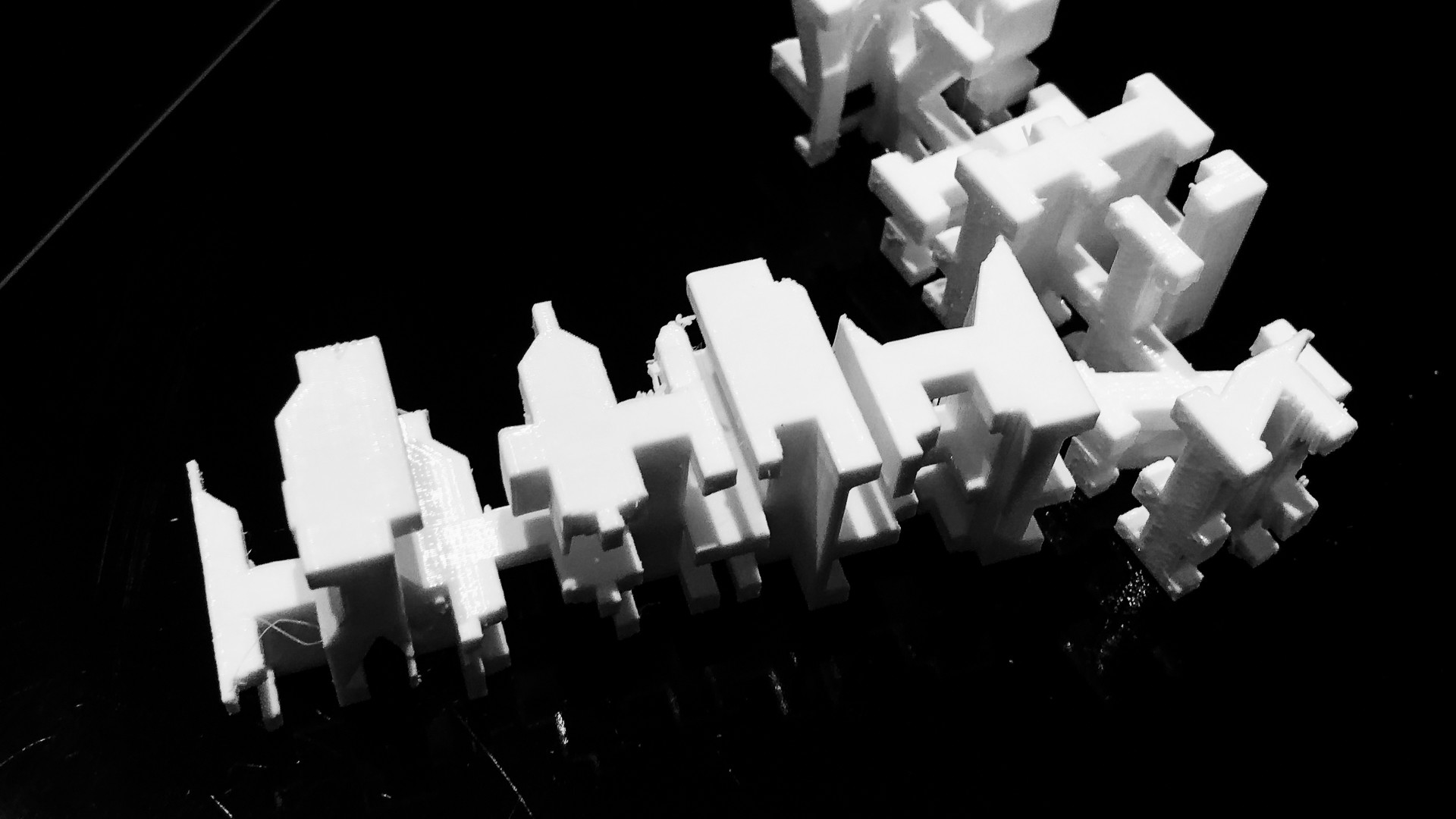
On another note - by way of delaying completion still further so I don’t have to address the looming “gcode-and-all-things-to-do-with-making-this-actually-work-lack-of-knowledge-crisis”, I’ve been fiddling on completely unimportant things at the end of the spectrum I do understand. Perhaps jealous too, of everyone who just seems to be able to get on with it. ![]()
I may never get the thing going, but it will be a nice ornament. Have I gone too far this time?
2 Likes
You will be surprised how simple gcode and CAM are. There are things to learn, for sure. But you can do it and you might just enjoy it. ![]()
2 Likes
Thanks Jeff, I can and I will! (but that doesn’t mean I can’t muck around putting it off for as long as possible! It was less than twelve months ago I was in the same muddle with the mysteries of CAD and 3d printing, and I managed that even without the incredible support that you blokes round here provide!
I’m trying not to think too far ahead though! ![]()
2 Likes
I love these sort of finishing touches. I am so surprised there have not been many more over the years. Keep it up!
1 Like
Thanks Ryan, will do! 
Well that was one of those three steps forward and one back kind of days.
Tired of the continuous internal arguments about whether to use an existing router or just get the one that’s proven I went off to the local big box tool shed, to discover that there’s been a bit of a rash of people building MPCNC derivatives apparently, because the Makita shelves were bare!  :
:

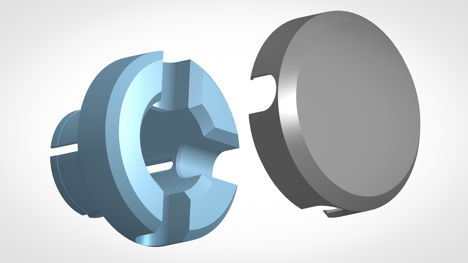
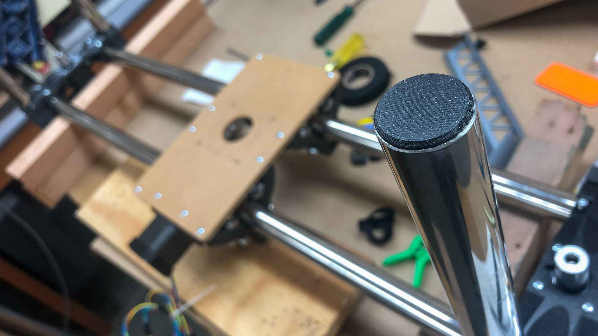
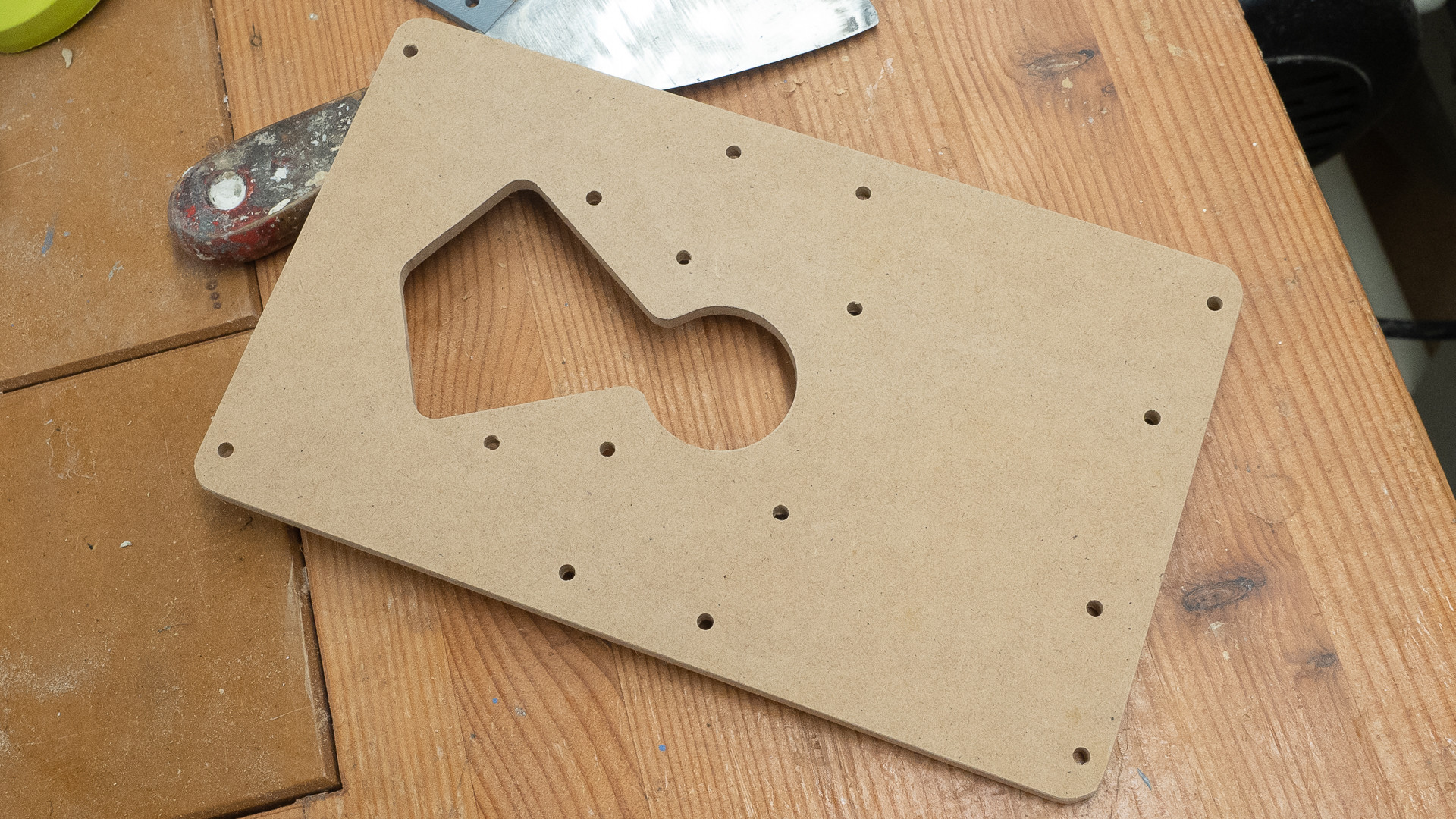
A few hours later I had one in my hot little hands, decision made time for a “710” plate! May as well get on with it while the things upside down. I did manage to get the “Legs” as close to square as the little bit of flex in the screw joints will allow (which is pretty true - measured across the underside of the plate ), and for good measure, made some little plugs for the bottoms of the tubes, to keep the mudwasps out.
Finally I had this great idea, because there’s barely enough branding on Ryan’s bits as it is, to do a cutout V1 logo on the stepper cover - I guess it could be ok with a bit more work and perhaps if it was backlit, but let’s put that one in the "good ideas that didn’t quite come off bin for now shall we?

1 Like
New Router = new base plate required. Just waiting for the paint to dry.
I’m not sure that this will be the long term configuration, but it will be the one that gets me going.
Well I’m going to blame Angus @Makers Muse for sending me down the Boolean Intersection rabbit hole yesterday. But in between a few quick sketches and an hour of picking out support material, I had plenty of time to contemplate the state of the LowRider, and I’ve concluded it’s a bit like a Boolean Intersection.
If I look at it from exactly the right angle, it all becomes clear!

I rebuilt the entire structure over a few pleasant hours, righting some wrongs, re-orienting all of the steppers to suit myself rather than following what some random dude on the internet did, and generally being grateful for the effort and skill @vicious1 has put into those parts. It’s great to know that when an issue arises it’s something I’ve done rather than a bit of ill design.
Case in point: I couldn’t feed one of the cable ties through the xz piece. A quick dash to my computer, stuck the part in the slicer, “x-rayed” it, and discovered that in one of my three alignment adventures I’d allowed the tube to creep over the little retainer lip, which then allowed the zip tie to catch. One more disassembly later, and I’d also solved the puzzle I’d had as to why it had taken so much effort to get the alignment of that part right!
It’s altogether, belts on, pretty much aligned, now waiting for some angle aluminium, and a roll of filament to arrive from Czechia.
1 Like
It feels like intermission!
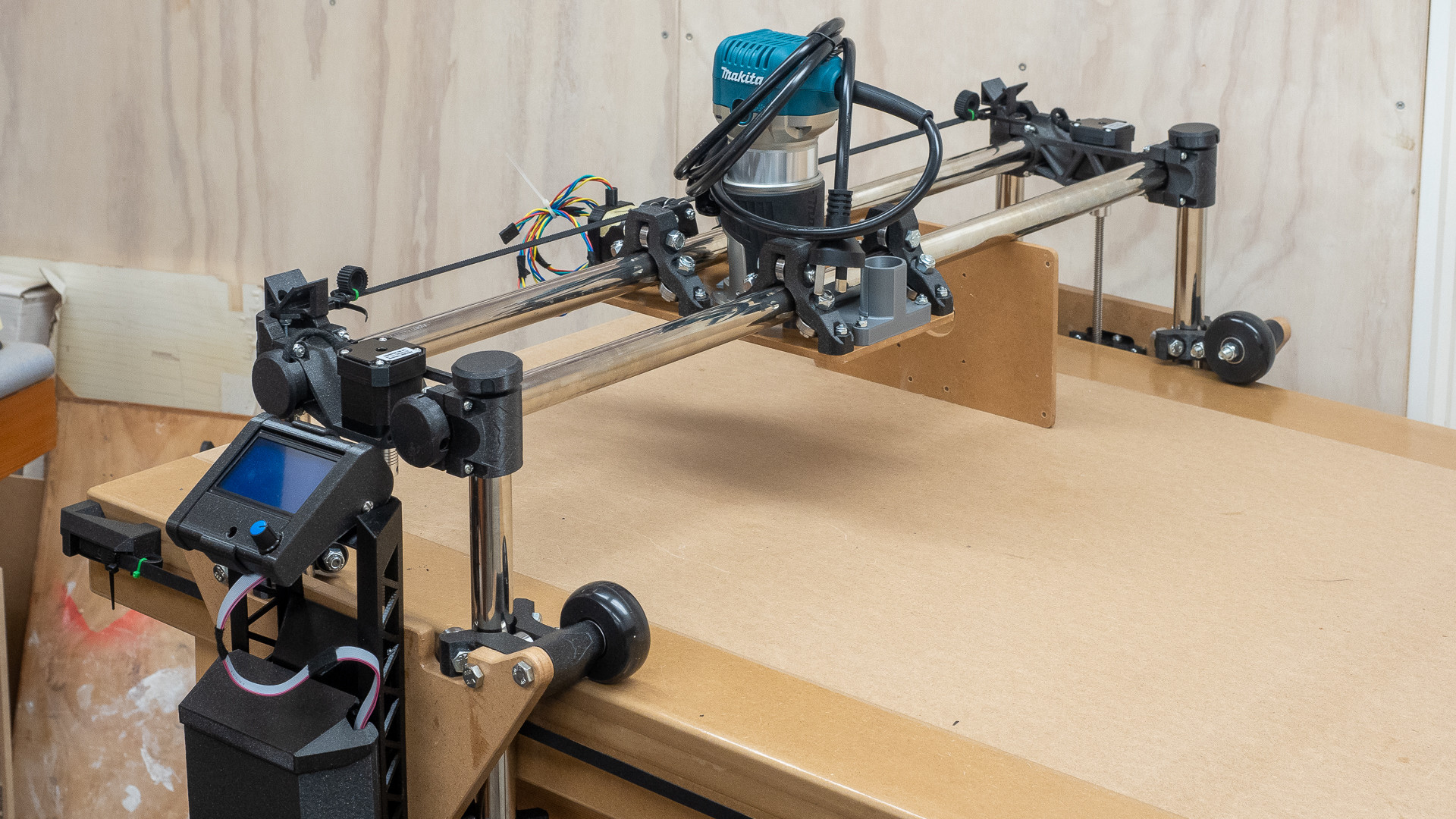
I’ve had a bit of a tidy up (of my mind as well), ready to play with wires. My USB C adaptor and cable have arrived so I should be ready to go with Repetier in a day or three, but there are a couple of other things that are likely to hold me up for a week or so, and I’m inclined to let it all sit until I can get a clear run.
So here’s the state of play.
2 Likes
on another thread @vicious1 said:
How do you know your tensioners are perfectly square?
This is part of the setup. Use your machine under power to mark all four corners of your work area and measure them diagonally. If the numbers are not the same or within a mm or two you need to move or shim one of the belt tensioners. Mine was built close enough to where I just use a few layers of blue tape to shim between the belt stop and Z rail.
…Which sent me scurrying for my tape measure. I guess this is why this forum is so magical, answers just fall out of the sky before you get to ask the question.
Had I known this of course, I would have taken a little more care installing the tensioners. Instead I just packed 'em off the edges with a bit of MDF, being only concerned that they looked good!
To cut to the chase - the diagonal is almost exactly 2mm out which doesn’t tell us a lot except that the maximum parallel error can be 2.5mm give or take - if I wasn’t in such illustrious company I’d be happy with that! ![]() As a worst case I guess I’ll be printing a shim!
As a worst case I guess I’ll be printing a shim!
I am really glad to have that little bit of understanding tucked away before the setup begins. Thanks.
1 Like
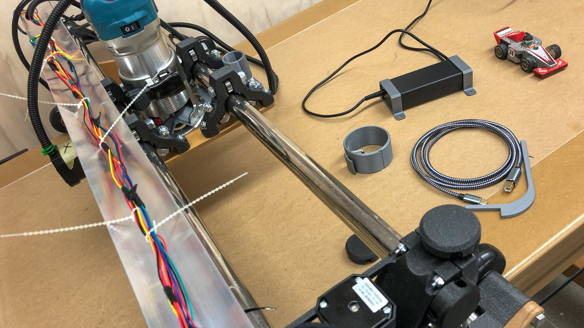
The ducks would appear to be in a row! USB C cable means I can plug the laptop in, pen adapter (thanks @SupraGuy is ready, aluminium angle resting in place (more on that next week), wiring temporarily loomed up more or less (I know not everyone is quite so obsessive about tidy wiring, but if it’s not in a neat bunch it just does my head in!) until some pins arrive in the post hopefully late next week and I can tidy it up a bit more), oh and I’ve made a couple of mounting brackets for the AC adapter so I can screw it under the table in due course, AND my filament arrived this evening as well.
I haven’t made up my mind whether to turn the router through 90° or not - I really don’t want to let that get in the way of progress for now.
Not sure if I’m going to get it fired up tomorrow, I have a problem. We are going away until the middle of next week so if I get it running and all is well I won’t be able to sleep wanting to get it finished. On the other hand if it doesn’t go as expected I won’t be able to sleep until it does.
4 Likes
If you’re the kind of person for whom building is the means to an end rather than a journey itself, it might pay to avert your gaze for a bit.
I thought I’d drill a few holes in the back of the Rambo case to hide a bit of wiring, and in the process remembered how I quite like using the step drill. The only thing lying around that looked as though it could do with a few dozen big holes drilled in it, was the aluminium angle that will one day carry the vac pipe.
So I spent a pleasant morning making a jig and drilling to my heart’s content, followed by a bit of a rub with Mother’s Mag Wheel polish for good measure. The printer is printing the final case mounts, we’re still going away for a few days, so it what nicer way to take my mind off firing the thing up? 
5 Likes
Now that is a fancy vac rail!
1 Like
Speed holes.
1 Like
Anyone else catch Vice Grip Garage on YouTube? “Weight reduction,” “direct venting,” and “speed holes” are common turns of phrase there.
3 Likes
One of my current favorite channels.
3 Likes
More on the “Joy of Building”:
I had to add a bit of weight back on today, I really don’t know what I did before I had a 3d printer and that wasn’t all that long ago!
I’ve worked out that when I set up the jig to drill the holes I had an error of about 0.2mm between the centres. Normally if I can cut somwhere along the line marked by a fat Sharpie I consider that to be a spectacular level of accuracy, I can’t ever remember being that close to anything before. Sadly when you have 30 holes in a row, that sized error creates a cumulative error of 6 mm or so which puts the bolt hole in the xy bracket in exactly the wrong spot.
Five minutes of drawing and ten minutes of printing (x4) and the problem mysteriously disappeared and it solved a problem with what to do with the holes that were partly obscured anyway.
2 Likes