Lowrider 2 build in Gothenburg, Sweden

I like the idea of having printed wheels because they will have a more consistent shape then the regular inline skate wheels.

What material will you print them with? Wont they be slippery?

Isn’t that what we would want? Less friction along the axis? There’s plenty of friction going on with the spindle, steppers, Z-lead screw, bearings; the wheels ought to not add to the problem. Plus, with how he will be removing the drift potential by using an L to keep the Y parallel one would think grip on the surface isn’t needed anymore.

I printed them in PLA. I was thinking of doing it in PETG, but I’m having problem to get the thing to stick to the print bed.

The friction of the wheels is quite low, but the weight of the machine seems to be enough to keep them rotating instead of sliding.

We’ll see how they fare when (if…) I get everything up and running.

@Qvast Any news regarding your V-shaped wheels?
I am just starting to build a LowRider2 and thought of printing such wheels in TPU with a shore hardness of A95.
This type of material feels just like the rubber of tougher wheels.

No further update. The wheels need to be either quite large, or the channel quite small.

Think I still do not understand the problem to the full extend.
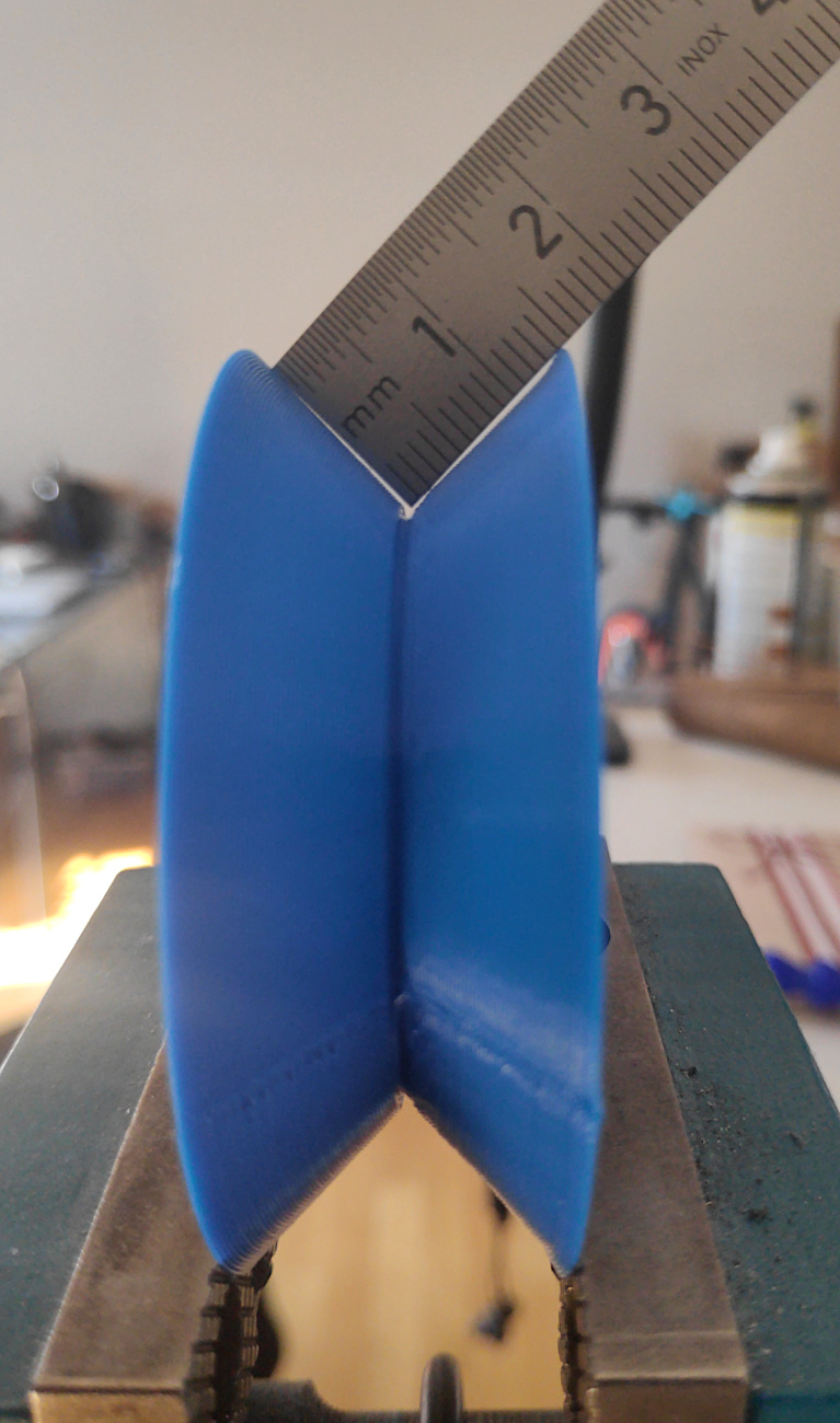
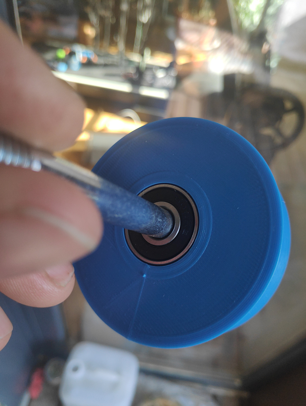
I just designed and printed a wheel with a inward groove 60mm heigh and 20mm wide in TPU.
The model can be downloaded from the prusa website here.
When I measure one side of the groove I get a bit less than 15 mm which would be ideal for a 15x15x2 mm L profile.
I still can not see where the L-profile will clash with the wheel brackets.
Please can you explain to me what my mistake in thinking is?

Here are some photos:


The problem is with the two inner rollers for the Z-axis. They are only approximately 7 mm of the ground, and will then hit the rail.

The yellow line is the ground level, and the arrows point at the problem:

1 Like

Ah, ok. Now I understand! :unamused: Thanks for clearing things up.

Did not take these rollers into consideration. Its a pity because the wheels with the groove would be kind of self centering and the upside down V channel could not be clogged with debris easily.

But thats life I think :stuck_out_tongue:

Can you just make the wheels bigger?

Yes - I thought of that too. Just will have to wait till I have started with my lowrider build so that I can measure how heigh the new wheels actually will have to be.
Right now they have a height of 60 mm. The height of the 15x15 channel should be around 10mm. When the Z-Roller is about 7mm above the board - like @Qvast said - the new wheels should be at least 2 x 3 = 6mm higher than this ones.
According to this calculation, a height of 60 + 6 + 2 mm clearence (=68mm) should be enough. :thinking: :grimacing:

The 7 millimeters was only an estimation, please measure yourself before you print. But yes, something like that should be enough.

I quite like the idea of inverse V wheels running on an L profiles fixed to the table. It would be fairly easy to ensure the profiles are parallel down the length of the table which would stop any slight wander. Also there would be less of a chance for dirt to build up to a level that would cause problems.

Would a PLA wheel hold up to the strain involved do you think?

I guess PLA would fail in the long term.
Probably TPU with a shore hardness around 95A would be a better choice. I reckon this is why the wheels of skateboards and shoe soles for example are made with a similar material in a similar hardness.
Here is a more detailed overview of TPU. In my experience it is not so difficult to print as it is described in the website mentioned above.
Polycarbonate or nylon might also be a good material for this purpose but I have to admit that I never have tried out any material under these circumstances :neutral_face: .

Yes - I will measure before I print the wheels.
Just used the numbers you provided for a rough estimation.
Thanks for sharing your experinces :+1:t3: !

I am still just at the point in my build of having a bag of 3D printed parts but I just measured on of the rollers and came up with a 6mm gap between the bottom of the bearing and the surface of the table.

So to make this work with a profile size any larger than 5mm above the table surface the diameter of the wheels is going to have to increase, unfortunately I don’t think you could go much larger on wheel diameter before it starts fowling on the roller body and bearing bolts.

I modified those parts for that very reason on mine. They look essentially flipped:

1 Like

Interesting idea, that would make the Y plates sit higher meaning you would need to have the rail lower than the work surface to retain the same Z height, as you show in your picture.

Looking at the 3D printed parts it would appear that the only piece that would need to be modifies would be the Y plate as you could just use the current 3D parts rotates and flipped to the other sides.

Also just noticed your Y stepper is inverted, I am guessing that the flipped rollers fowled against the belt in the original location?

Yes exactly, but I wanted the rail lower anyway to make it easier to slide large sheet goods on and off without contacting the rail so it worked out perfectly for me. You could try just flipping the existing parts, but there were subtle differences so to be safe I modified them in CAD by splitting the part and flipping just the wheel mount portion and then re-joining.

If I remember, the normal Y stepper configuration put the belts too high for me. I’m using EMT conduit and pulley wheels to keep things centered, and the normal configuration would’ve put the belt mounts too close or overlapping with the conduit, so I just flipped it. I don’t remember any actual obstruction with the flipped parts but I could be wrong.

Well I’ve had a quick mess around with some CAD files this afternoon.

Comparing the two Y Rollers it would seem to me that you could just swap them over and rotate them without any need for modification. Using some 15x15mm angle and wheels with an OD of 50mm and an ID of 30mmwould raise the Y plate by approx 21mm.

From what I can tell the belt would clear the inverted roller assembly’s but, due to the Y plate sitting higher, the belts would now be above the table surface rather than beside it. It would make sense to me to do as Josh has done and flip the Y stepper assembly’s to lower the belt down placing them beside the table again.

I am not quite sure what the ID of the wheels would be?
All in all it looks quite promising - cant wait till my all my parts come and I can start building.