Heh, I start with the cold sweats and such when I open the CAD program… To each their own I guess. 
Well… I didn’t read all the responses before I went to onshape…
[attachment file=“screenshot-2019-01-28-1548714836.png”]

Wow, Onshape got the same answer I did, probably a lot faster too, though it wouldn’t have been for me. I’d have had to Google for 45 minutes or so to figure out how to draw the first circle.
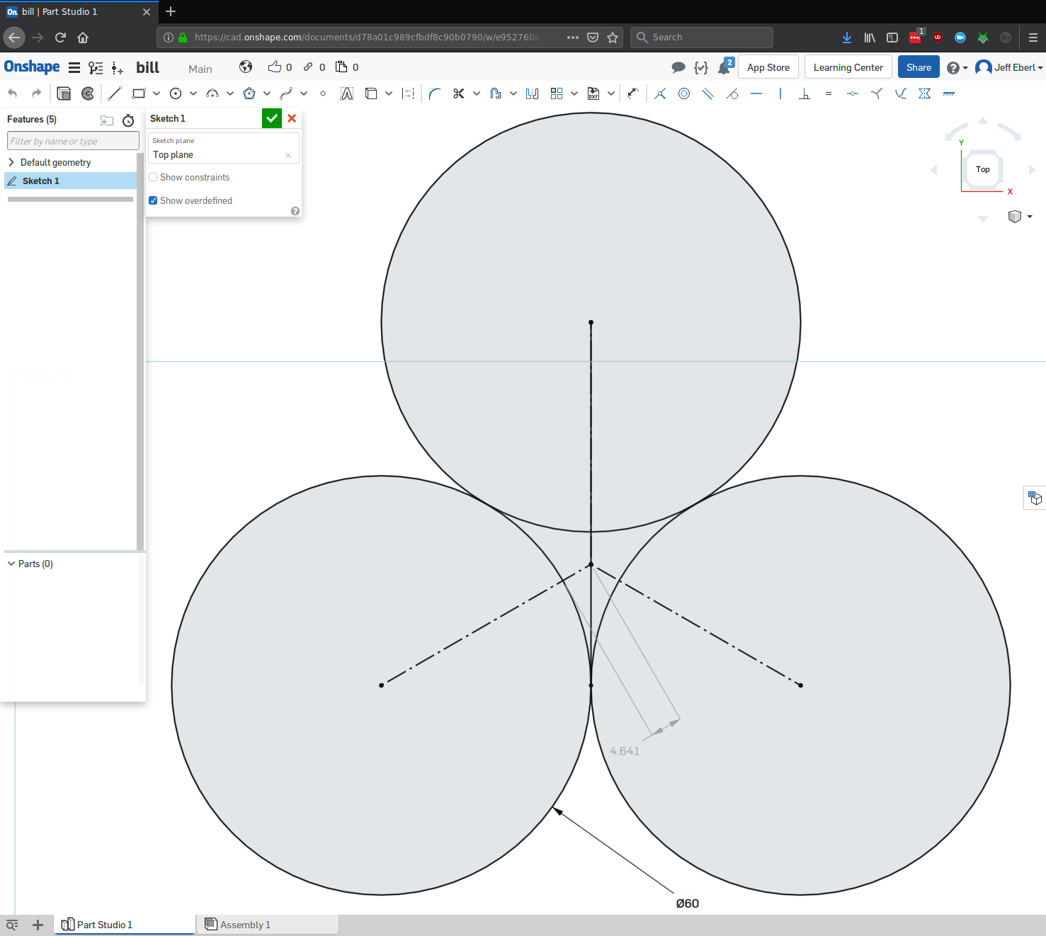
Just over 9mm, which meets our spec.
So, I ordered wheels and bearings from Ryan, and the pivots and thrust bearings from Amazon. I think if I use an appropriate Loctite on the threads I won’t needs thrust bearings on the outsides… Or maybe on just one outside.
Now, are the pivots screws/nuts going to interfere with the spacing between the four layers? I’m thinking the base to arm link is spaced by the thrust bearing, the arm to petal is also spaced by the thrust bearing, and the petal to ring is spaced by the final thrust bearing.
So, current BOM looks like:
Cut Pieces
- Base *2
- Ankle *2
- Outer Stand *1
- Arm *3
- Petal *3
- Inner Ring *1
Hardware - Pivot nut and screw *9
- Thrust Bearing *9
- Wheels *3
10} Wheel Bearing *6 - Wheel Axle *3 (carriage bolt and nut, M8 or 5/16?)
Am I missing anything obvious at this point? Will I need a spacer between the wheel and petal? I’m working off the assumption I can have a square hole in the petal and use a carriage bolt to hold it, with a minimum of 2" diameter, less the bolt hole I believe it’ll be unlikely to break away. No real side forces unless things go horribly wrong, and in that case I’ll be too busy calling 911 (or staring at the hole in the garage wall, and in the neighbor’s truck, and their garage, and …) to worry about the breakage.
And onward, I chose to purchase some M8 carriage bolts, in various lengths to likely fit the need, as well as flanged nylon lock nuts to match. I figure the flange will potentially work a bit better for holding to the inner race of the bearing. Specs call for a square hole 7.5 mm on a side, but since the round bolt portion is M8, it might be better to use an 8mm square hole:
Head style: Carriage
Head height Min: 4.12mm
Head height Max: 4.88mm
Square width Min: 7.42mm
Square width Max: 8.58mm
I believe the Square width max number to be the diagonal across the square… Note the bolt head height is under the 5mm used by the thrust bearings, so we shouldn’t drag until we actually hit the inner ring. Maybe we should mount the wheels on the outer stand side of the petals? That might allow retraction to the full size of the inner ring instead of stopping when the wheels hit.
Anyone know anything about springs? I’m going to need to source them and decide how they will best mount. I’m thinking eye bolts into the outer stand and inner ring with the springs tying them together It might take a bit of fanegaling to best place them so they don’t interfere with the arms…
Still waiting on the thrust bearings and pivot bolts, but I picked up some Home Despot springs that might work. I also got what looks to be appropriate eye screws, they have 1/2" screw depth and 1/2" eye. I’ll add them to the eventual BOM.
Bill have you gotten any hardware? Going to be laid up for a while
I have what I believe to be all the hardware and a friend has been working on the drawings for me. He uses Corel Draw though, so it’s not quite CAD worthy. He’s also trying to change the design on me in several places and I have to argue to get them back to my design. ;(
[attachment file=96225]
Note that in this ‘final’ design he has the petals opening backwards, trying to push the wheels open while the lathe is spinning counter-clockwise. The positioning of the arms also forces the maximum size to be smaller, but at least that’s wide enough for my needs. One suggestion we came up with that works is the order of the layers. I had said outer, arm, petal, inner and what actually should work better is outer, petal and inner, arm. That should have a bunch less slop when assembled. With the inner circle flush against the outer we could add some bearings to act as rollers around the outside. Note that when I say ‘flush’ I really mean ‘a thrust bearing depth apart’.

1 Like
Looks like the board glitched on me and generated two posts. So this one is not the same as the previous one.
Bill, it sounds like you’ve got a good project to get serious about learning CAD. You’ve done the hard work on the design, now just figure out how to use the tools.
Yeah, I get three or four hours in to learning how to do it in a CAD program, then get frustrated and set it aside. My mind really doesn’t want me to be doing CAD… 
Paul just built one.
Yeah, I ended up deciding to just buy the right type of lathe for cue work. I never could get a set of drawings I could take to the MPCNC to build it.