I have a LR4 that I built a few months ago and I am very happy with it. I own a laser engraver that I use to cut veneer but the working surface is only 400x400 mm. I want therefore to use my LR4 with the laser to have a bigger surface.
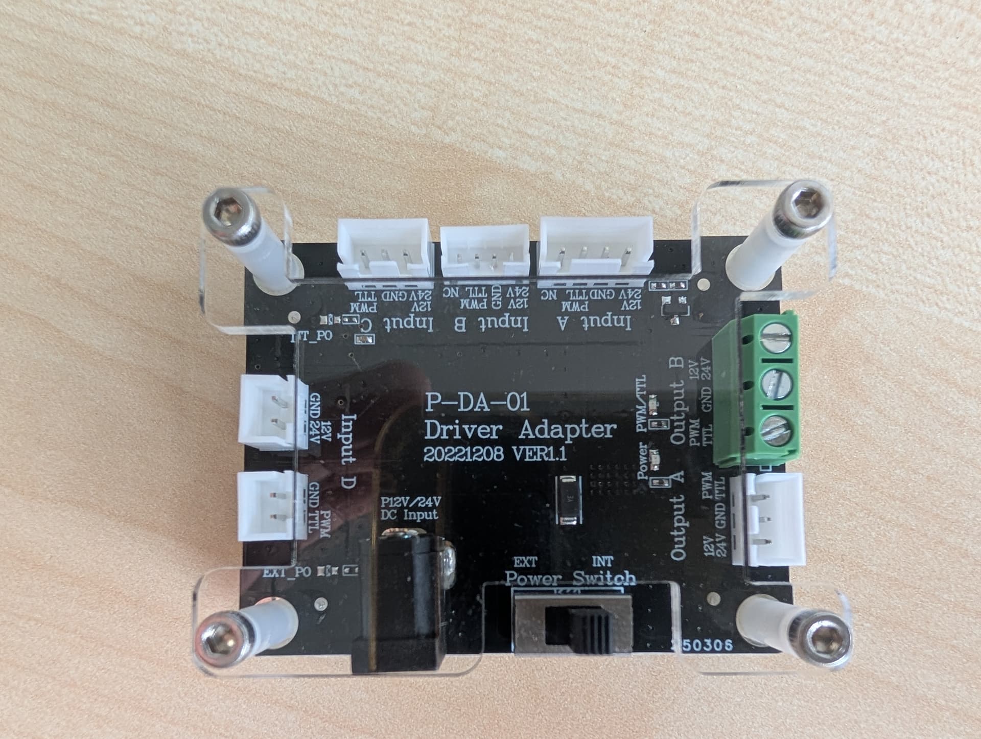
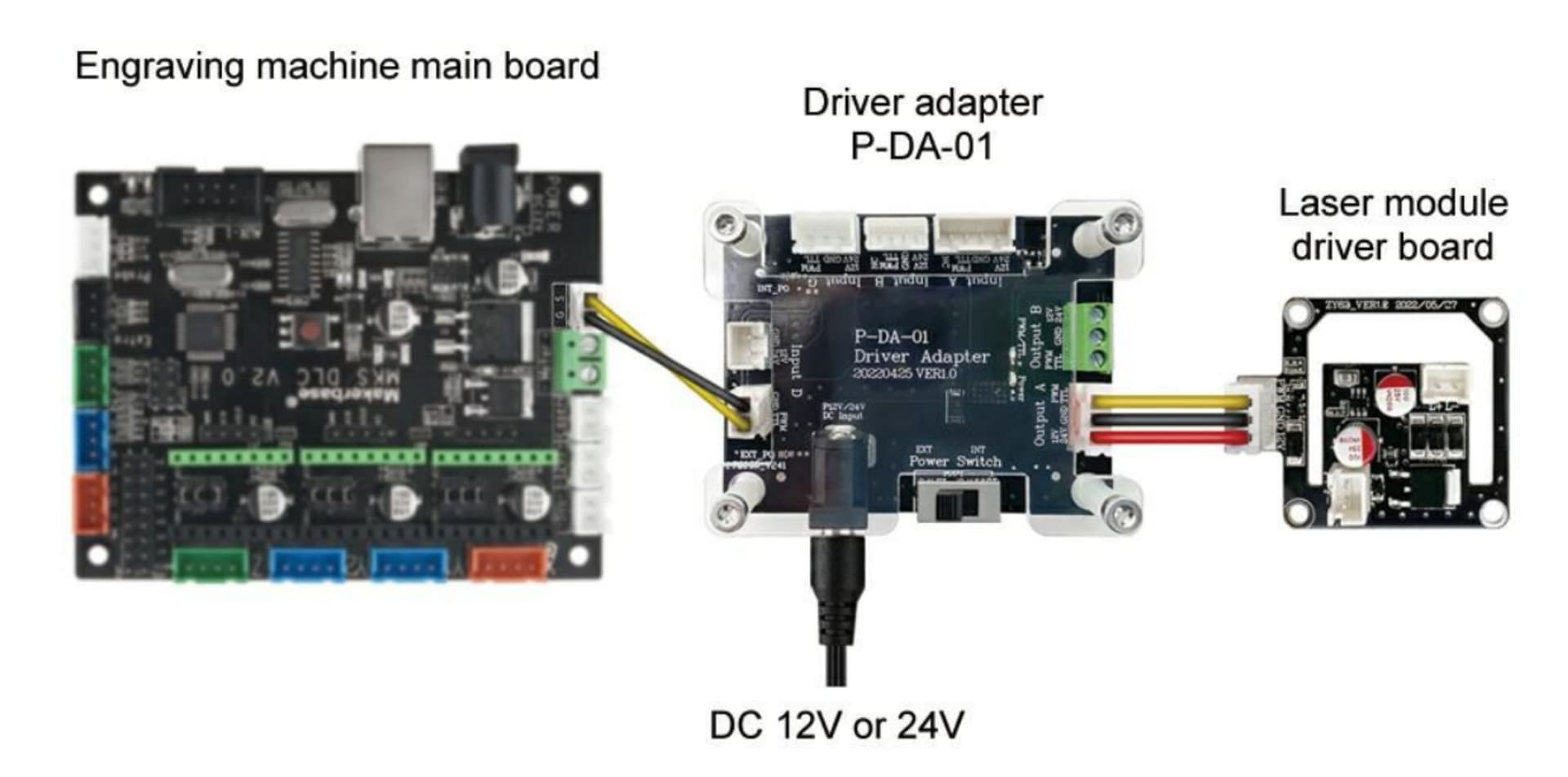
I have a Laser Tree LT-80W-AA PRO that came with the Driver Adapter P-DA-01.
I am an illiterate for electronics and I would need your help to understand how to wire it.
Based on the manual I have the following options.
directly connect the laser with the 3 pin connector to the Jackpot (no 3 pin connector on Jackpot)
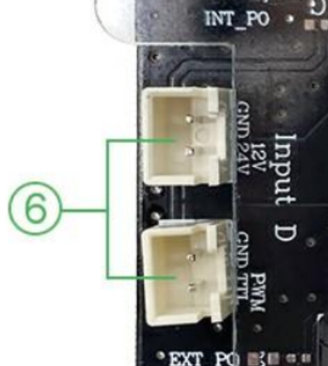
connect the laser to the adapter and then the adapter to the Jackpot with a 2 pin connector (no 2 pin connector on Jackpot)
Am I correct to assume that I would have to strip the pin and connect directly the wires? If yes, can I connect directly the laser or do I need the adapter?
Its really easy: one of the connection in the board its for TTL+GND thats whats you are going to use to connect to the 5V output in the jackpot.
The other one says 12/24v input: thats the connection to the power source and the laser module: even if the input is 12v you should share the gnd connection to the board.
That adapter board should be used between the diode and the jackpot
Its been ages since i did my diode laser and answered from my head, i hope i didnt make a mistake.
I have the same Laser Tree unit (on my SKR Pro v1.2 LR3). You do not need to connect the adapter module, as long as the laser module is the same voltage as the power supply for the Jackpot (the Laser Tree comes in both 12V and 24V options).
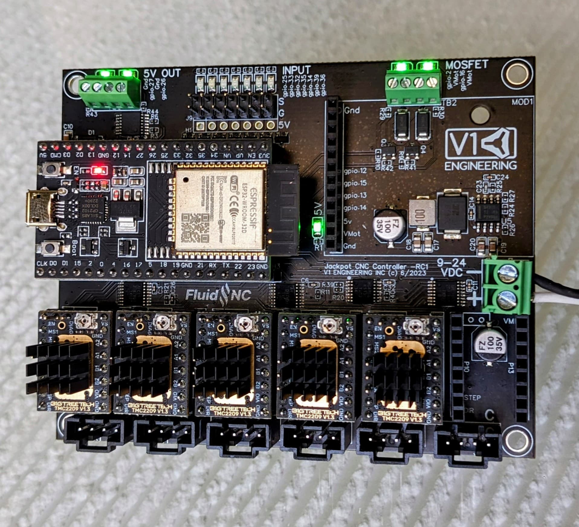
If both Jackpot and Laser Tree Laser Module are 24V, connect the + power (red) lead from the laser module to the 24V+ terminal of the Jackpot. Connect the GND (black) lead from the module to the 24V-(GND) terminal of the Jackpot, and connect the PWM (yellow) lead from the laser module to the PWM output terminal of the Jackpot.
Note that the Laser module requires at least 80W power, and the jackpot requires around 60W (I think), so the stock power supply from V1E may not have enough capacity to drive both units. You may need a more powerful (larger) power supply.
Ok. since my Laser is 12 V I will use an external power supply going to the Adapter and then connect the adapter to the Jackpot via the Adapter 2-pin connector GDN/PWM TTL on the Adaper and then on the Jackpot on gpio.26 OR gpio.27. Correct?
The adapter module MAY (or may not) provide this function already. The best way to tell would be to use a DMM (multimeter/Ohmmeter) to test for resistance between the -12V (GND) terminal and the PWM GND terminal on the adapter module. If there is 0 Ohms (or less than 0.5 Ohms) between the two, you probably don’t need a 5th wire. Otherwise, you need to tie the two power supply -(GND) wires together at a common potential (voltage).
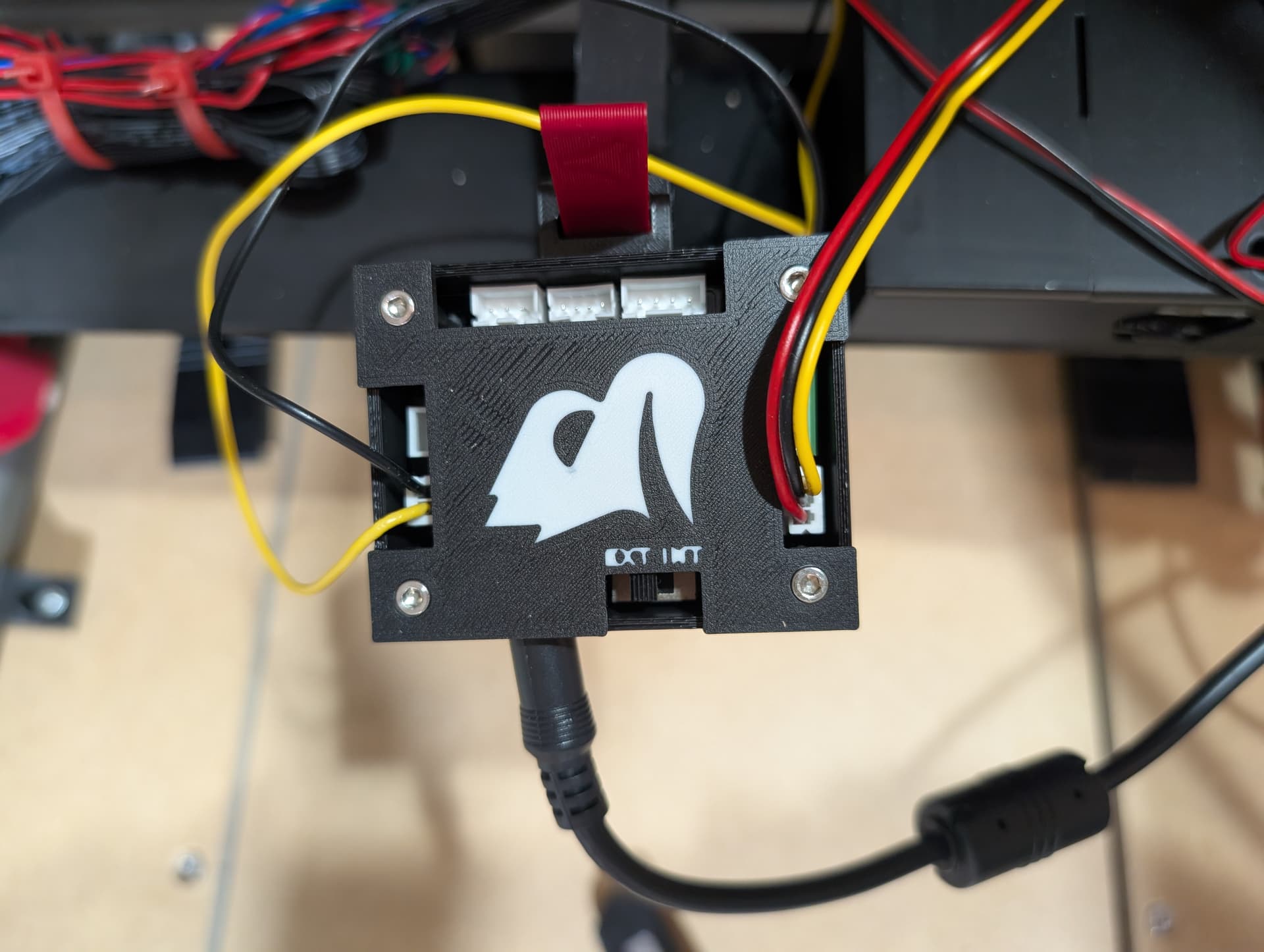
Withe the YELLOW wire going to gpio.27 and the BLACK wire going in the corresponding GDN on the Jackpot (top left in the pic below, the two connections on the left). I assume that this means there is no need to have a common ground between the power supplies.
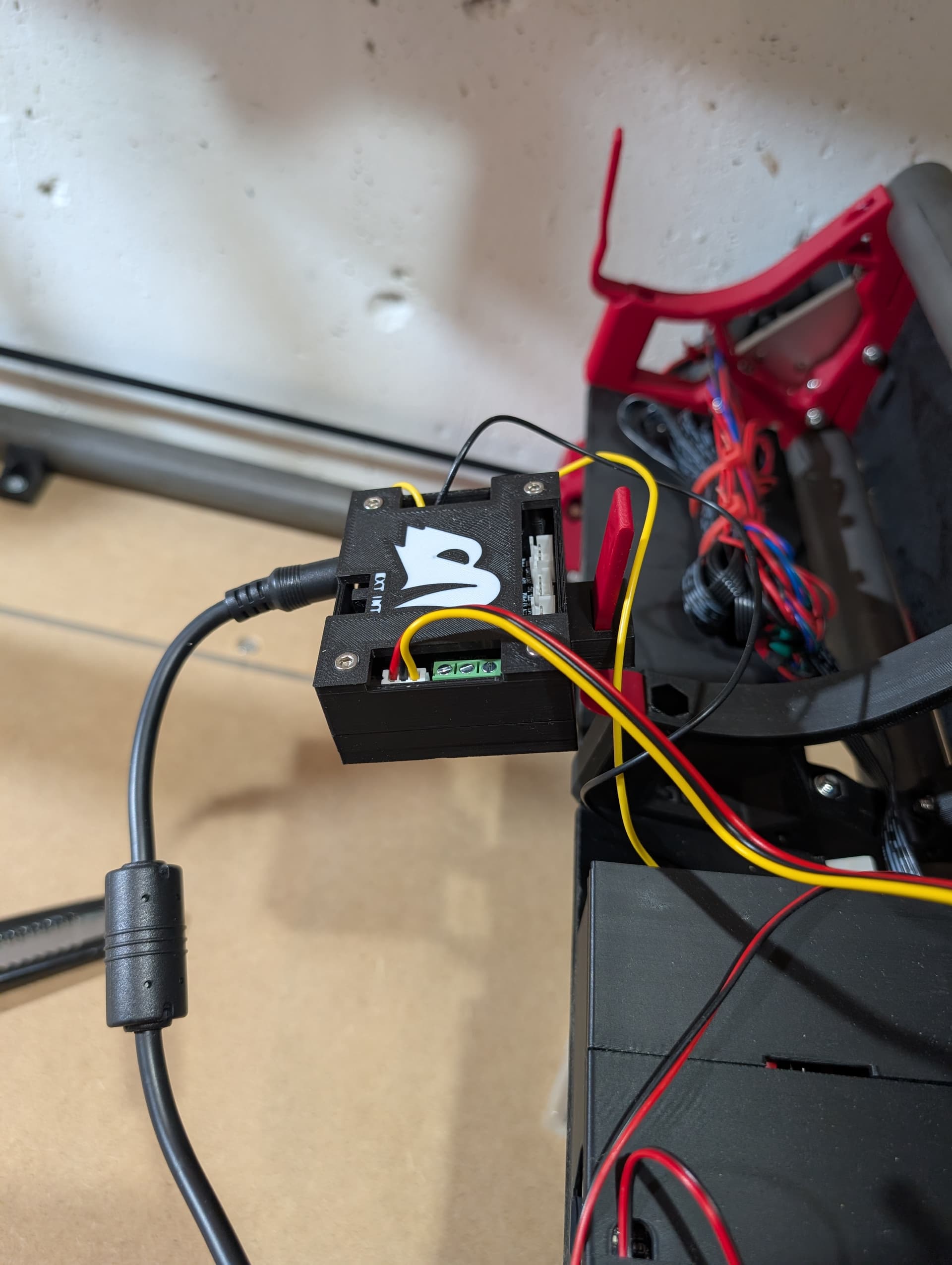
I connected the red power line to my laser tree to the mosfet driven power output, I’m running on 24v, then yellow line to gpio.27, then black wire to board ground with the power supply.
Don’t forget to uncomment the laser section of your config.yaml. Paste this into your config:
Then make sure you configure Lightburn to use 1000 as max speed, (it usually is already, but make sure) in laser tools → machine or device I can’t remember which