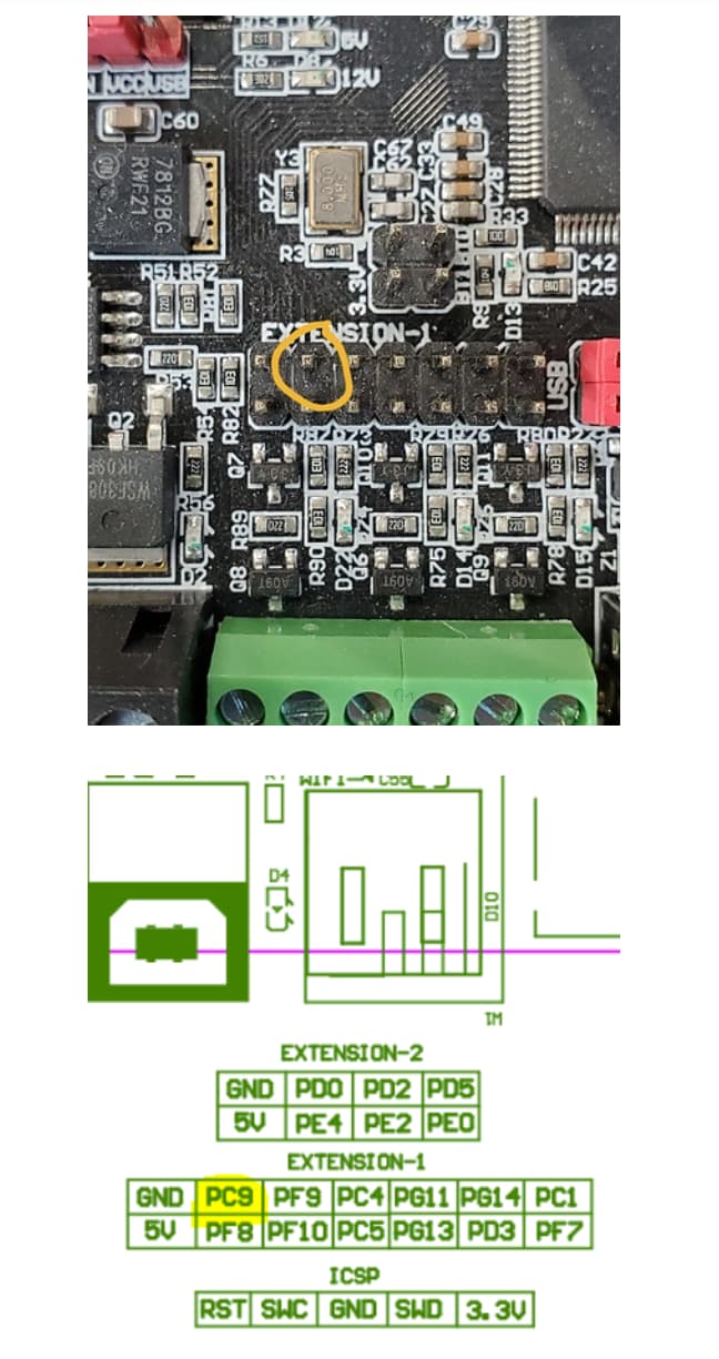
Hello all. I installed a J-tech quade pro 24 laser and noticed that I’m not getting full power output. I m running an SKR Pro 1.2, with 24VDC input power. I’m hooked up to PC9 and GND, but when I send the board Gcode M3 S255, it only reads 3.2 VDC signal out hooked up to a digital volt meter. Display is removed while testing, Firmare is what was shipped.
Most lasers work with PWM, not analogue voltages. The Pulse Width Modulation alters the duty cycle from zero (off) to 100% (full). A multi meter will average out the signal to show an analogue value between zero and whatever the processor runs on (in your case 3v3)… so…your results sounds about right to me, your instruction (M3S255) is telling the uP to turn PC9 pin on 100% duty cycle and as the uP operates at 3v3 that is what you are reading.
What you really need is an oscilloscope to see the signal trace, however, if you send an M3S127 you should see a 50% duty cycle of 3v3 on the scope, which your meter will average out to around 1v7, that will show your PWM is working ok.
No, you are not wrong, remember the signal pin PC9 is only capable of being driven between ground and 3v3, what is important is the duty cycle. However it is displayed from the firmware Tom, it is still the PWM duty cycle that drives the laser. The firmware options will just confuse the OP even further.
Checking the Jteck manual. The input signal can be anything greater than 2.8V up to 24 voltages. There is no need for you to change the voltage. Power is controlled by the PWM only. Are you using their controller? They have a very good troubleshooting manual online for your laser. Here is a quick paste of the manual.
The driver board has a selector switch for the two different modes of the board.
• Input Control Mode: This is when the switch is on the RIGHT. This mode allows for a signal to be
connected to connectors H2 or H4 for a signal to turn the laser on and off. Use this input with your
controller to turn the laser on and off with G Code commands.
• CW Mode: This is when the switch is on the LEFT. This mode stands for “Constant Wave”, which means
that the laser will turn on and stay on until the switch is turned back to the right or the power on the
board is turned off. This is useful for troubleshooting that the laser is working properly.
CONTROL SIGNAL AND PERFORMANCE
The input connection provides an optically isolated input for control of the laser diode. The connection and the
jumper settings were described in the previous sections. The voltage required to turn on the opto-isolator is 2.8
volts. The input can handle up to 24 volts. The input can be cycled with no degradation up to 3KHz. It will work
with 3.3V, 5.0V and 12V, 24V logic boards from various manufacturers like National Instruments.
Thanks! I had a fundamental misunderstanding in that the PWM is actually a frequency signal, and that the J-tech Driver board actually controls the power based on that.
The only thing I don’t understand is that when I did the first cutting test on 6 circles on 1/4 inch wood. It etched the first outline, but didn’t pass thru it(probably a feed-rate thing - then moved to the next circle and the laser didn’t turn on. I bought his machine to have the cutting flexibility, but this behavior looks like a duty cycle thing.
I don’t have any experience with the SK Pro. I’m sure others here have far more experience. Since it appears that you can run the driver in manual mode. I would test the laser operation manualy to verify its operation. Posibbilites of errors are programming of of inverted signals.For a fun test of this, simply test at 50% power. Then decrease the power to 25%. If the laser decreases you know your logic is correct. If it increases then the logic is inverted.
The problem might be in the g-code and not in the hardware setup, so check the g-code. If you upload your g-code to a forum post, someone can take a look.
No, what I am referring to is most controller systems can be programmed for the output to follow the input or opposite. Normal input 1= 1 output
Inverted. Input 1= 0 output
The effect in this case is that the laser pulse width is either 1 or not/1