Tweak one endstop. did you double check that all 4 sides are actually 40cm?
2 Likes
No, X axis was 40cm (or maybe 39.8), but Y axis was almost 39.5cm everytime.
I have tweaked one endstop since!
But this is the result I get:

After one 40x40 it becomes a line gets offset when it starts to draw the square the second time.
Tweaking the endstop didn’t make it more or less square then before.
Have you checked the grub screws on your Y pulleys? If the configuration for steps per mm is the same on both axes but the actual length moved is different from the commanded move on Y, then there’s most likely something mechanical wrong on that axis. Grub screws has been the culprit multiple times.
1 Like
Y is my short axis, and I did check the grub screws on that pulley a couple of days ago. I unscrewed it and screwed it back. Seem to have been OKEY before and after.
1 Like
I am quite lost in why this is happening.
- I’ve checked grub screws.
- The pipes are square with the plastic parts holding them and so on.
- Gantry pipes is square to the Z-axis pipes
- Wheels are tightened perfectly so they have no wiggle room side to side.
- It doesn’t rub against the table
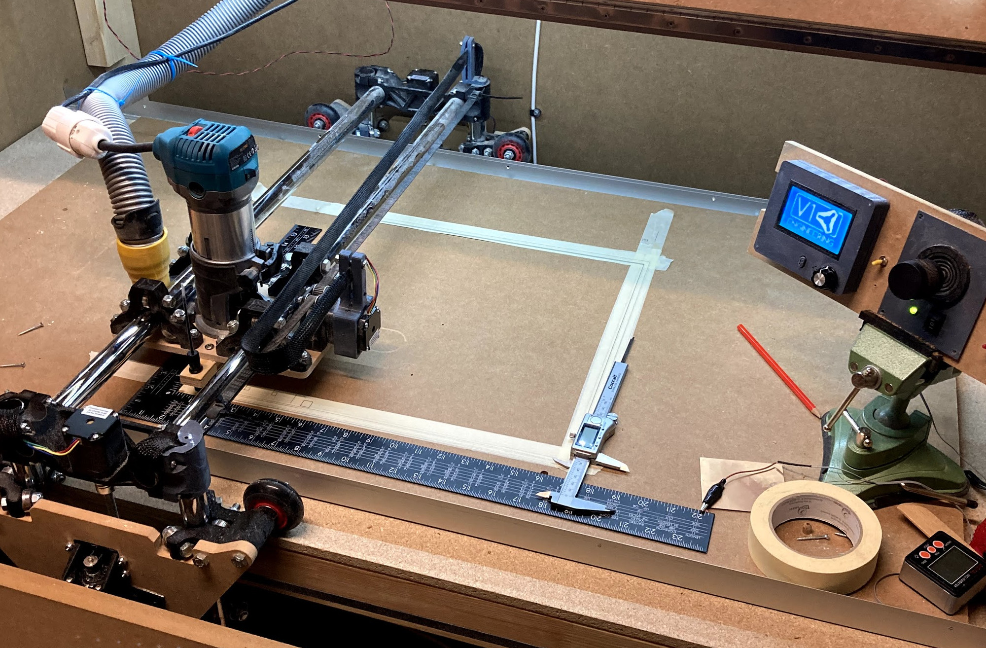
- Machine feels quite solid in all directions when trying to move it by hand with steppers on.
Actually the X-belts (my long axis) are rubbing against Z-pipes. But I guess that is not that big of a issue. Will fix this with some shims in the belt holders.
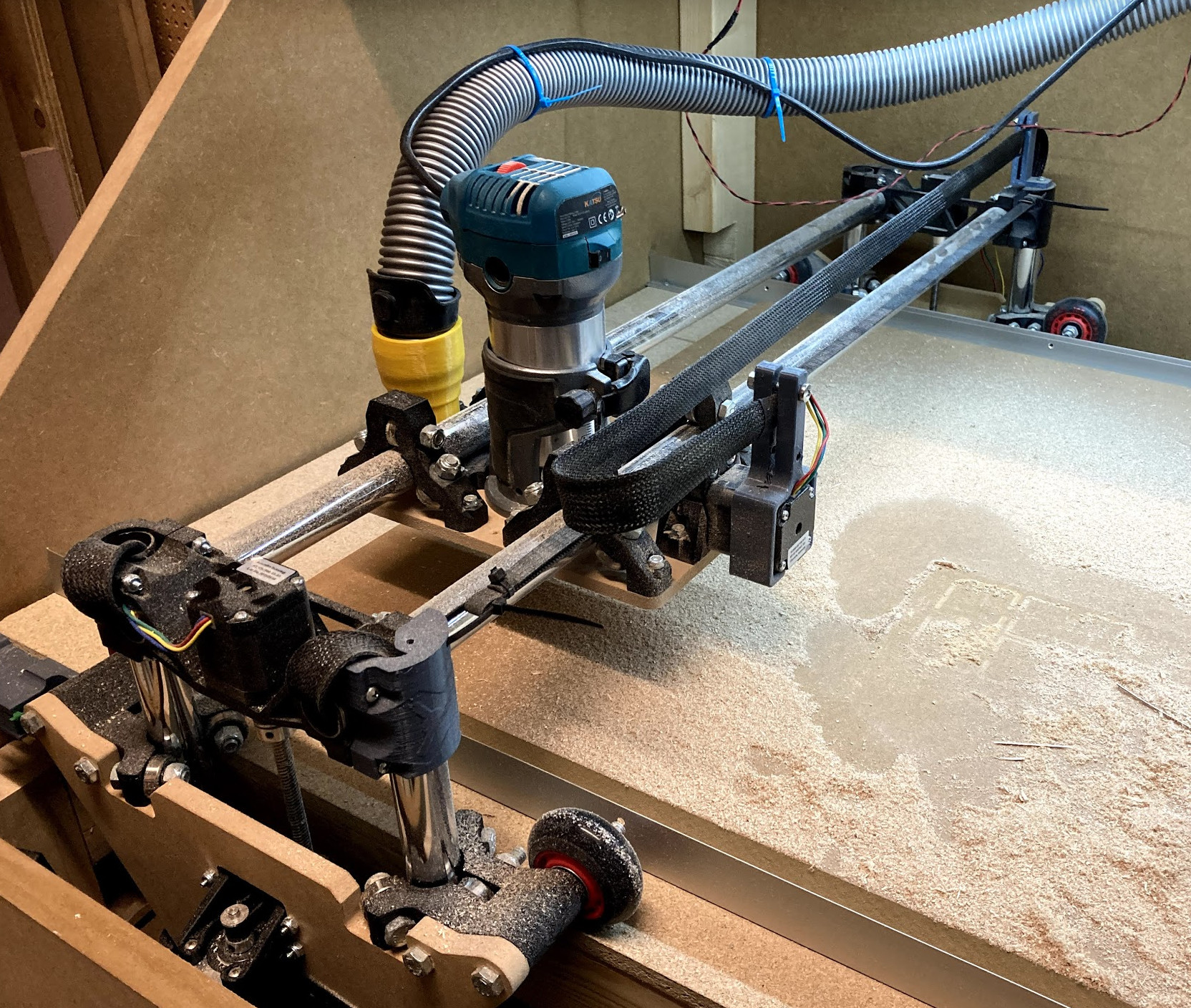

Looks like a solid machine. Is the double line caused by the wheels slipping to the side?
1 Like
I don’t know! But I did some measuring now since you asked! So now I know 
- I ran the machine 40x40cm like before.
- I measured the left wheel at the end of each square
- Made 5 squares
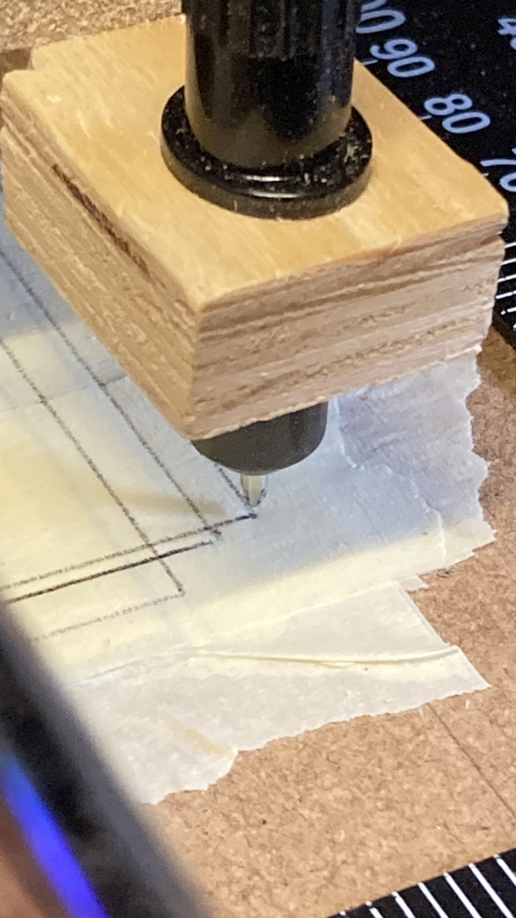
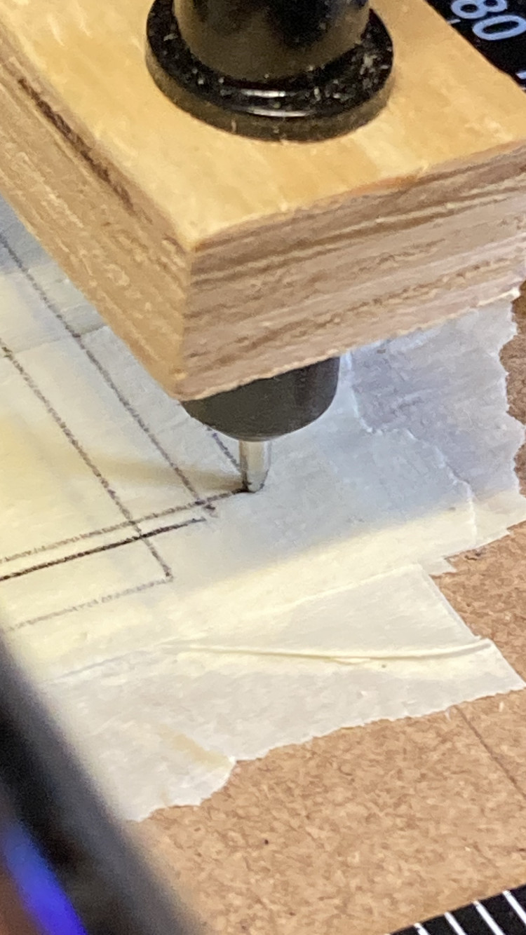
Measured like this:
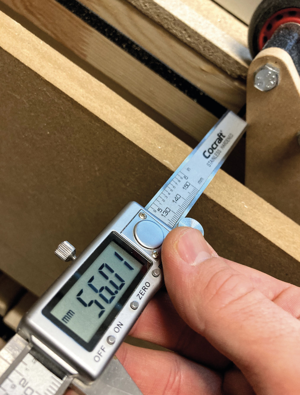
This are the results at the end of each square:
- 53.68
- 53.84 (+0.16)
- 54.39 (+0.55)
- 55.34 (+0.95)
- 56.01 (+0.67)
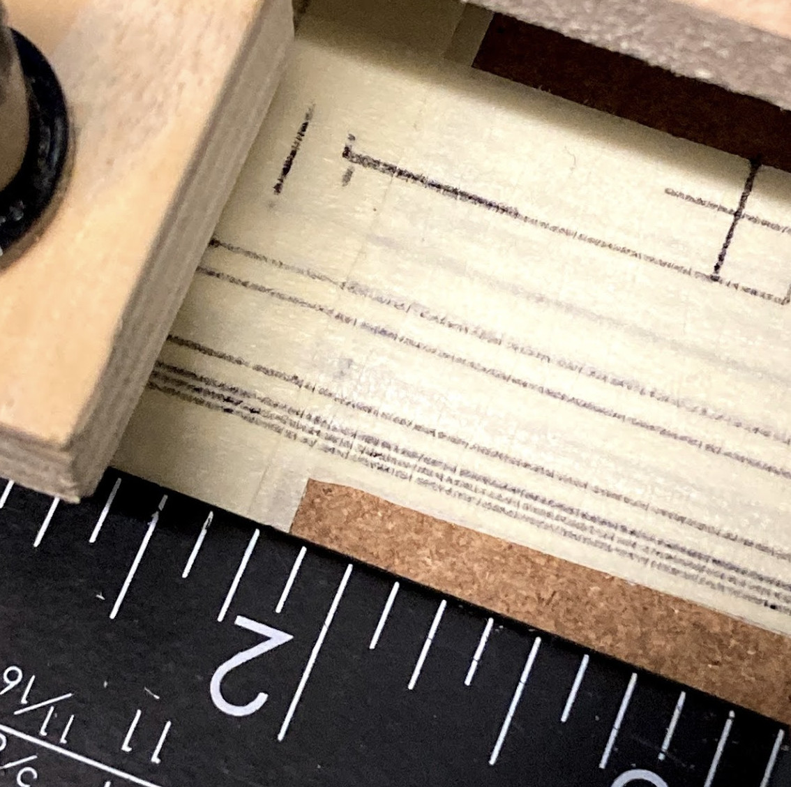
And this is how the lines look hehehe
I had this trouble, and I installed 3/4"x3/4" plywood tracks just inside the wheels. The wheels drag on it a little, but it has consistent position in X.
Some other people have used 3/4" aluminum angle brackets, or routed a small groove in the table for the wheels to ride in.
1 Like
Yes, I’ve seen that… But I didn’t know if it was a good idea. But since you tell me this I will start sketching up my version of it! Thanks!
Questions about it:
- Will the friction caused by the wheels dragging on the guide rail affect the cut?
- Is it enough to set up a guide rail for just one side and let the other side run with a guide rail?
I like the small groove also… Seems easier to achieve, but harder to tweak if it goes wrong.
Also, is this the reason why it does draw a 90 degree square?
If you overdo it, I am sure it will. I just used a nail gun to tack them down, using the gantry as a guide, making sure the first one was square to the table. I will say that you can make this bind. You don’t want that. It should travel straight on its own. This is just to cut off the worst offense. If you get it within a fraction of a mm or just touching, it will be more precise than that fraction of a mm.
IDK. You could try that but I would guess whatever force causes it to go to one side is reversed when travelling back. Your numbers went up and then down, so that kind of strengthens that argument.
Thanks Jeffe!
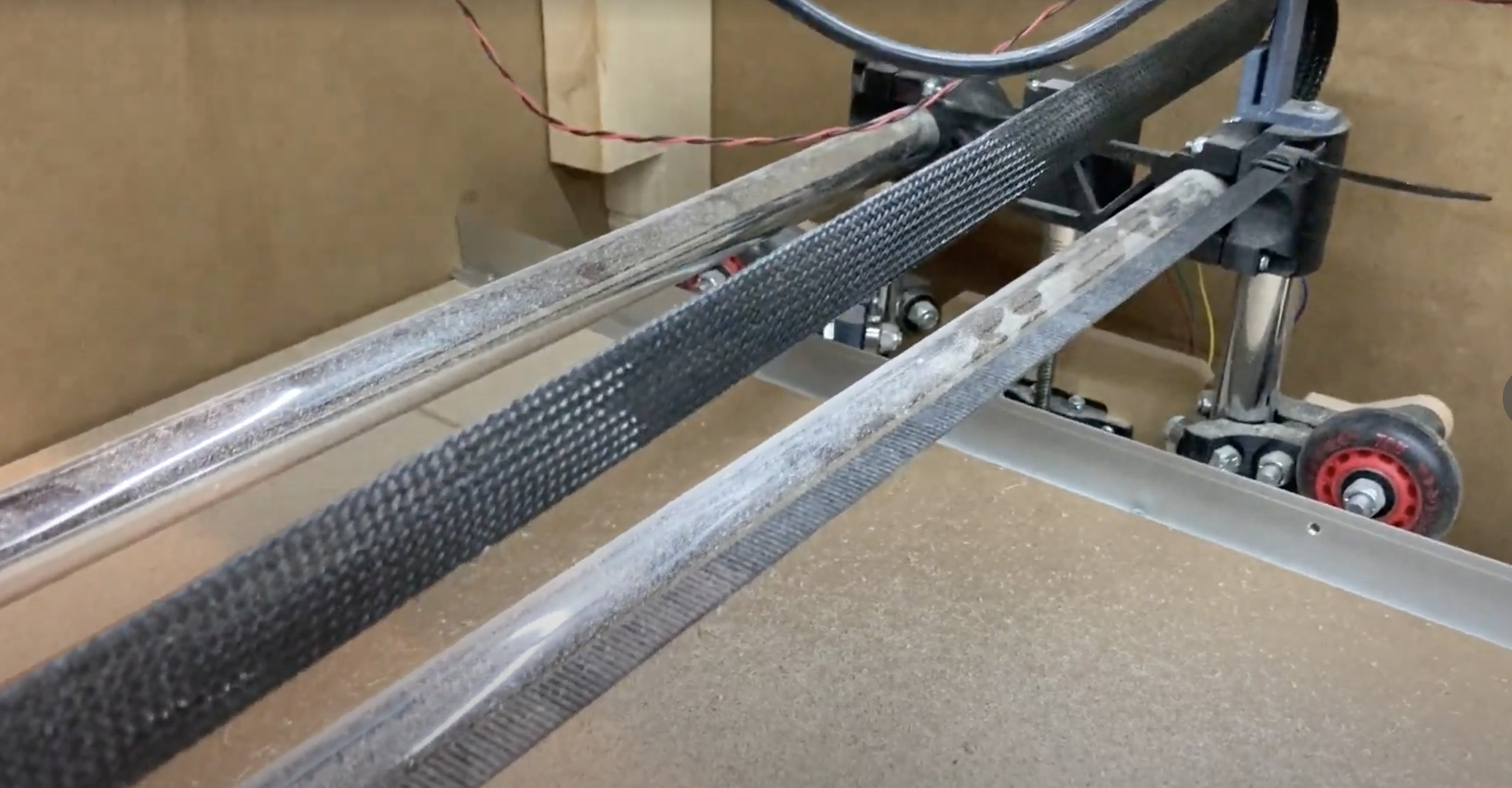
I also just noticed this…
Between these points I get following measurement… It is the center point of the wheel axis:
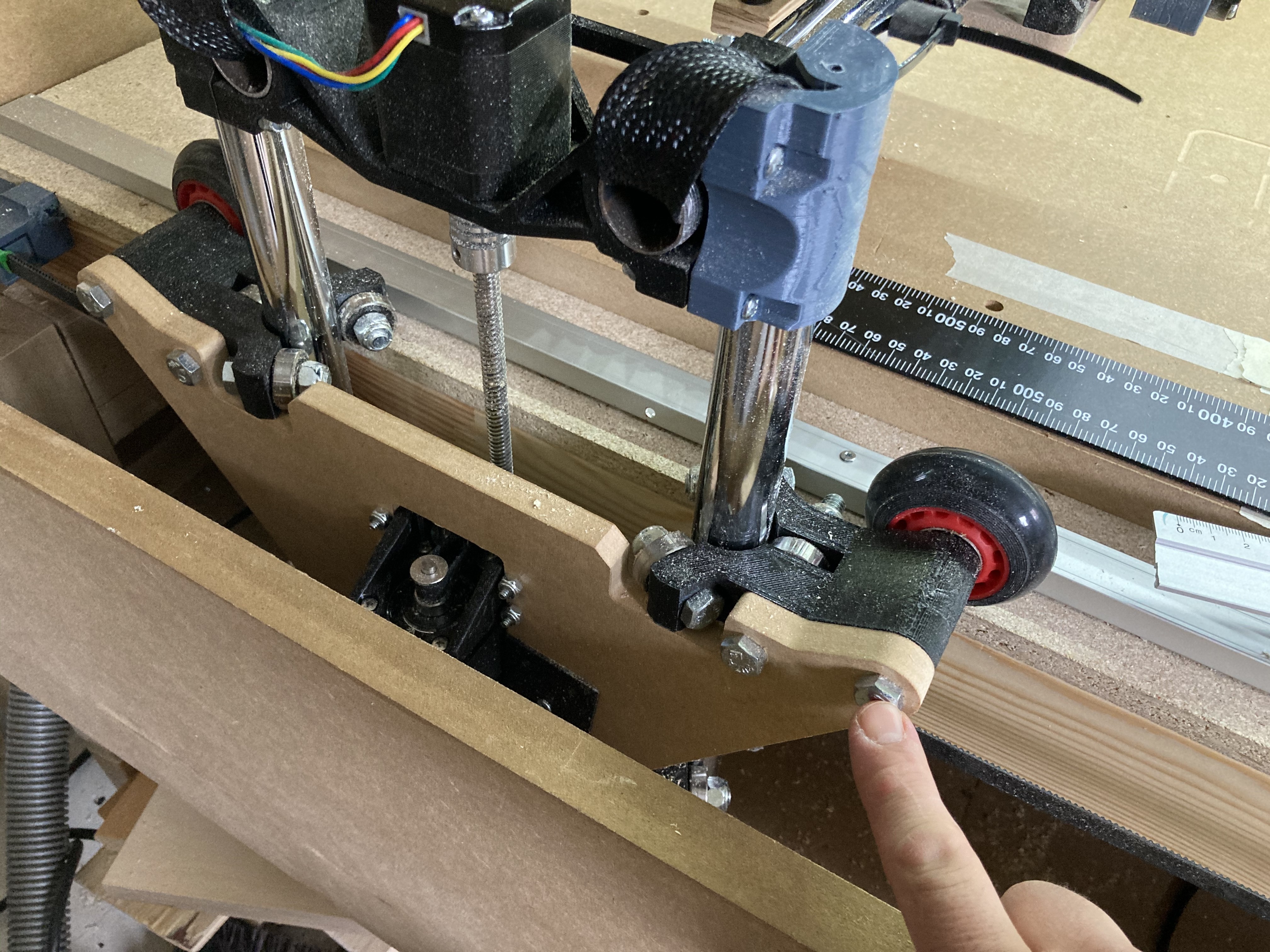
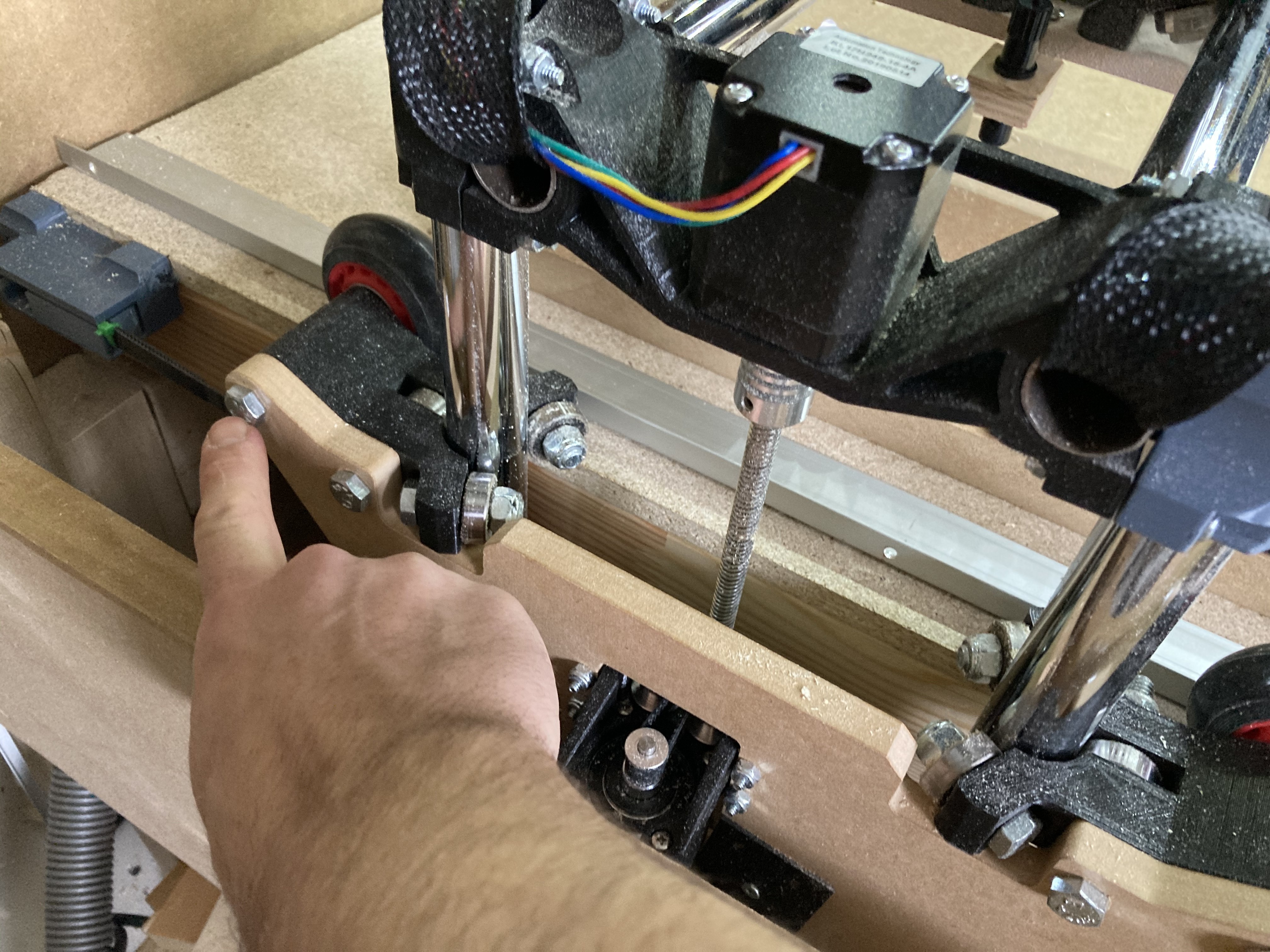
Outside: 308mm
Inside: 304.5mm
So they bow in a bit. That will surely cause problem I guess. The sides are 12mm MDF.
I will try to make a metal part that brings the wheels axis to square in the inside. If that makes sense.
1 Like
little off topic: are you using custom belt tensioners? Can you share them?
Thanks
1 Like
Excellent! Thanks
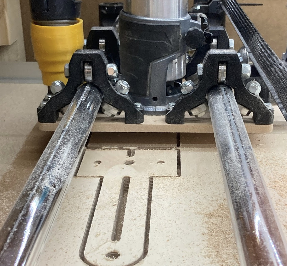
Okey so I have done some metal work.
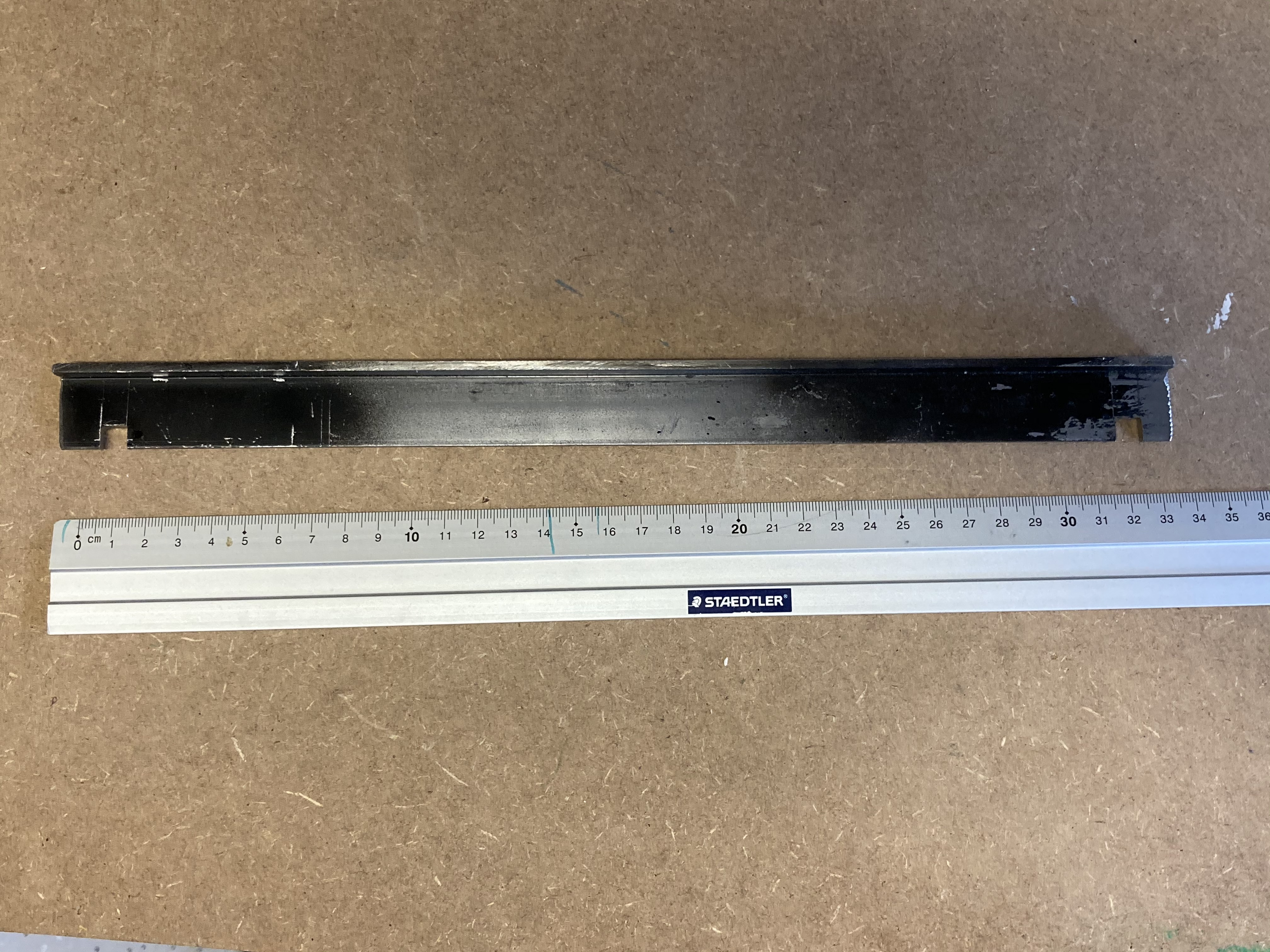
I made one for each side. And they should hold the wheels axis perfectly parallels to each other. At least that is the theory.

I have done some 40x40cm drawings again and this time the pen tip stops exactly where it started!
Success!
But it still doesn’t draw 90 degrees angles. The square is not square. It is still a parallelogram. It has gotten a bit better tho. But not enough.
So my guess: adjust physical end stops until square is square.
Maybe?
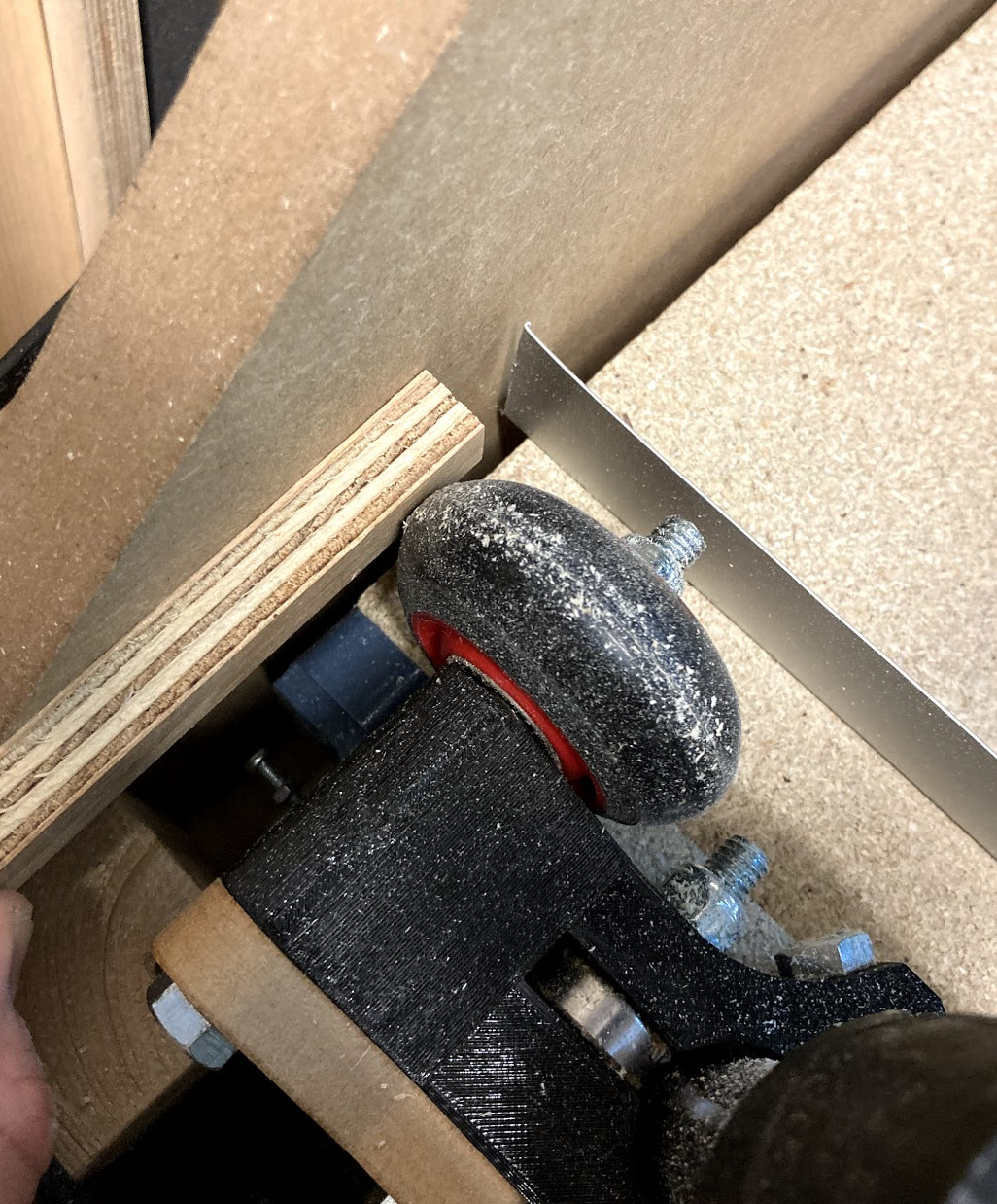
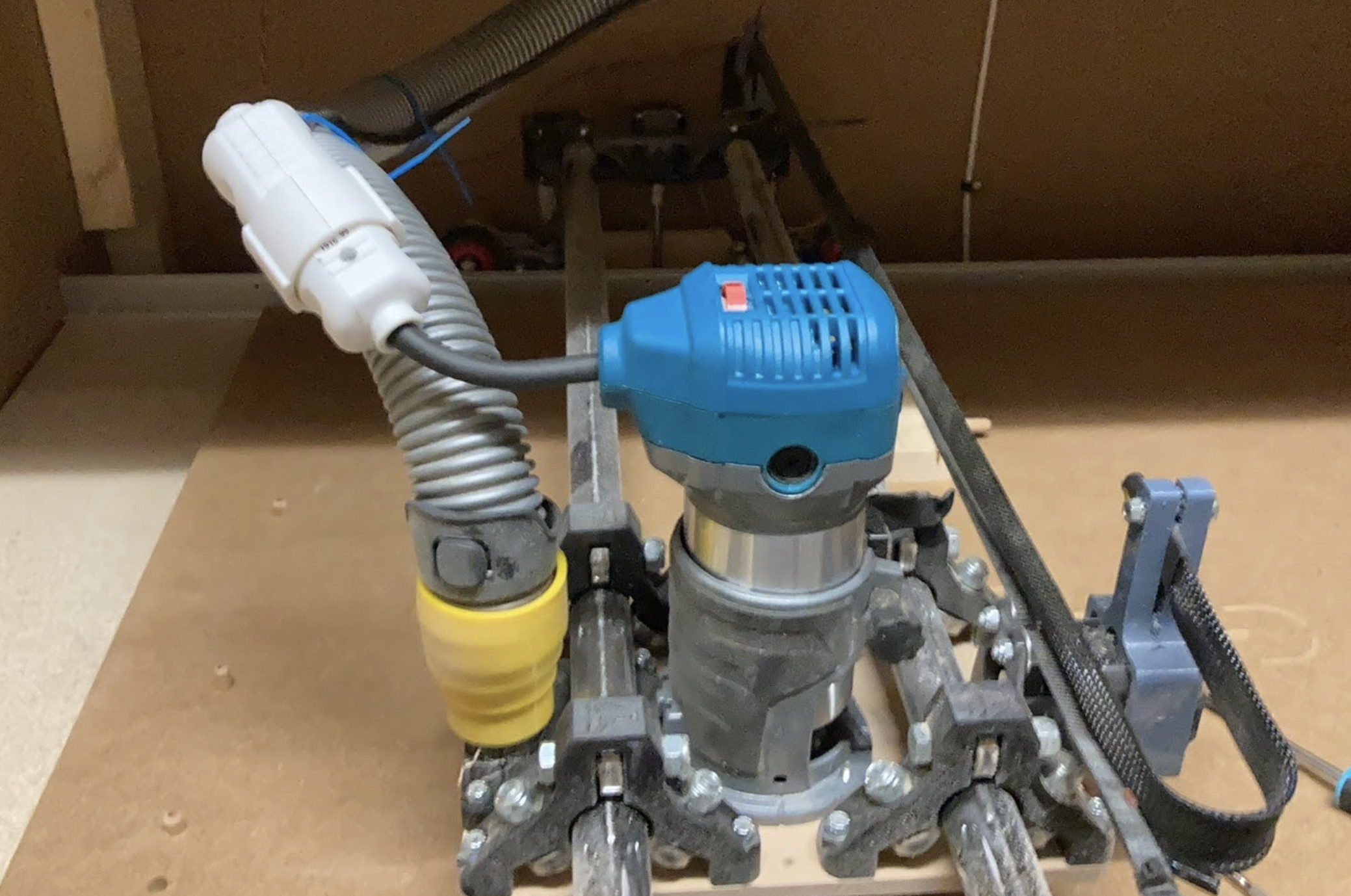
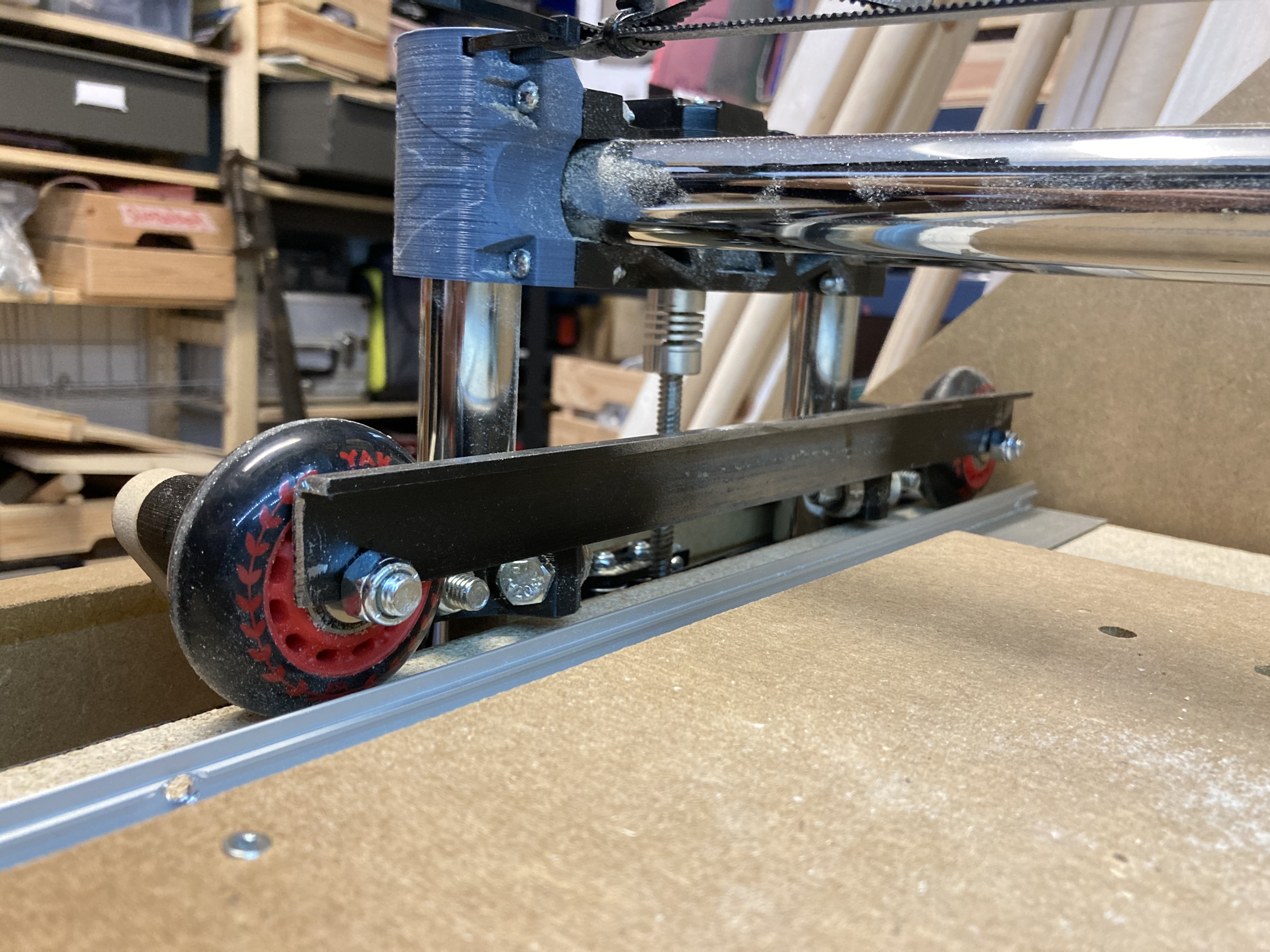
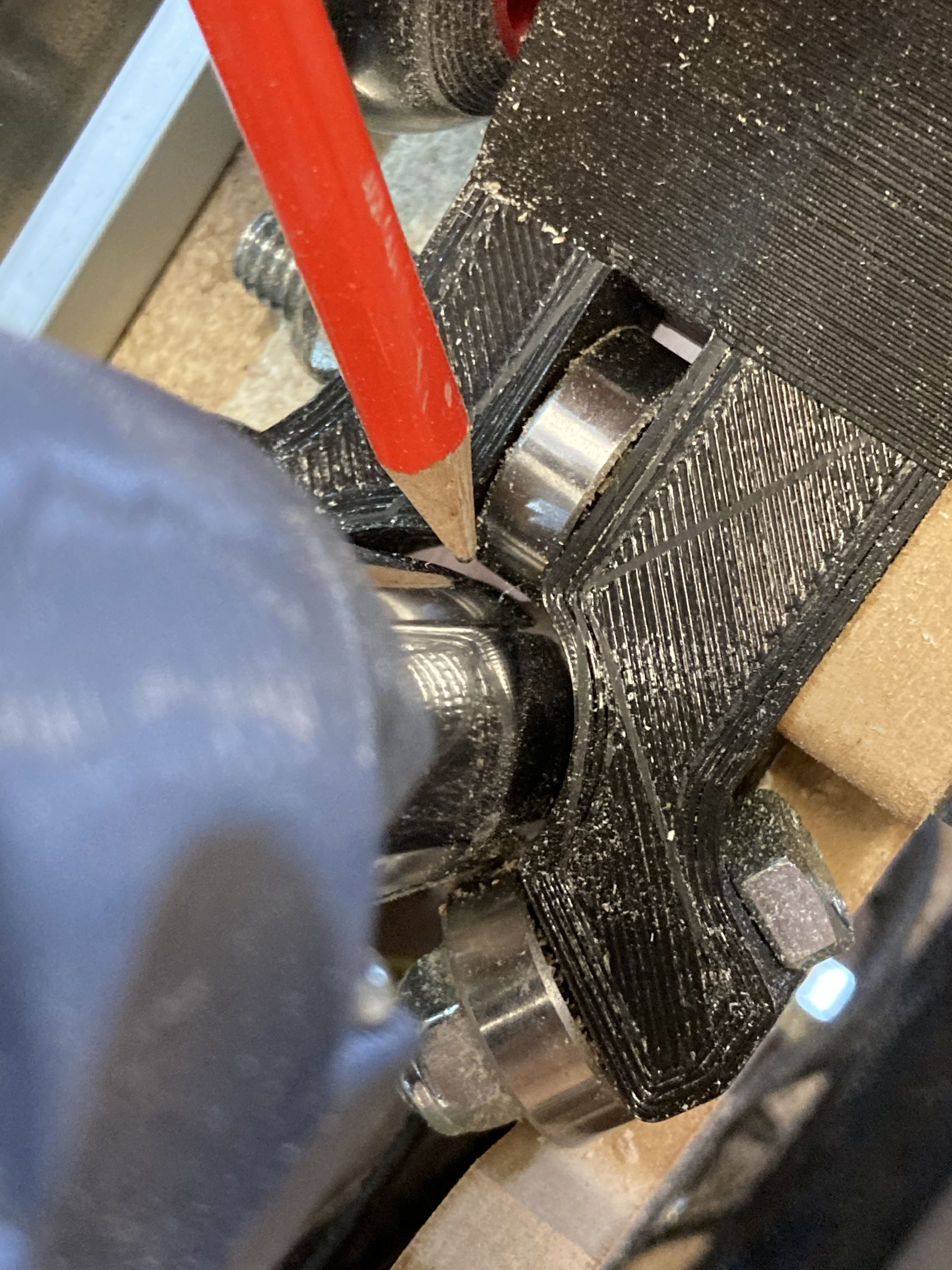
Even tho my metal brackets put them in parallel. The bearing on the Z axis doesn’t touch the pipes anymore. @vicious1 should I be worried about this? The machine runs true now, but as you see on this image, one of the bearings doesn’t touch the pipe anymore.
I am not great at helping with the bearing/mechanical questions, so I will skip that
But to make it square, you probably have it right. The motors need to start square and then they will travel in lockstep and be fine. I have some chunks of wood I clamp down and I hole the machine up against them when I power on the machine and I send a movement away from the blocks to start the machine.
1 Like
Okey. So I did some more test runs.
I haven’t adjusted the physical end stops because I knew I made sure to put those end stops as square as possible when mounting them… So I tested with them as is. And prayed.
And the machine now runs true!! At least when I draw a 40x40cm in the middle of the table.
So the issue in this case was that all my wheels was pointing in different directions so I needed to force them into alignment with a metal bracket. Maybe I should make a tutorial of that for others in need too.
@jeffeb3 thank you for spending time and keeping me going on solving this issue. I didn’t do the guide rails even tho I had the material. Amazing to brainstorm with u. Thanks!
2 Likes
Could be several things.Your Z rails might not be parallel, see if the gap changes from all the way down to all the way up. You might have the Z clamp flipped, one side has a small lip, or you could be above the lip causing a tilt.
1 Like
Just a heads up, you can mount those angle brackets along the backside of the MDF plates. I had to do that on mine. I also have one bearing that is not touching but it hasn’t been a problem. I run mine along tracks as well and fine tuned the spacing/wheel to track clearance with washers behind the wheels.
Great solution with the angle bracket! Care to share a link for that X axis wiring clamp on the stepper?