Help develop MP3DP v5!?!

Ryan, two things about twisting belts:

At the point they cross and contact each other, they are going to wear and produce a lot of dust (been there, done that). Try putting a thin piece of PTFE or UHMW between them. That might lead to static generation, but the belts will last a lot longer.

There is some relationship between the width of the belt, the allowable amount of twist, and the distance between the pulleys that was explained in a Gates (?) paper I have lost track of and been unable to find online. It looks to me like you have much too short a distance for a 180 degree twist for that belt width.

Also, why aren’t the motors located at the other two corners of the machine where there is a single pulley for each belt? Adding a bunch of extra idlers will add to the load on the motors (possibly limiting speed) and reduce belt life.

I ran into a problem in Arrakis’ predecessor where the belts ran on the inside of the t-slot frame. The tension on the 6 mm belts was sufficient to bow the 45 mm square t-slot pieces outward. Granted, those were very long pieces of t-slot, but your t-slot is much smaller and more flexible, and it looks like you have 9 or 10mm wide belts. t-slot is pretty cheap stuff. I’d go for a larger cross section to ensure minimal flexure due to belt tension.

t-slot is nice stuff if you have to move mechanical attachments around or don’t know exactly where they will be in advance, but it’s expensive and flexible compared to equivalent size square tubing, and you’re planning everything very carefully, so you won’t have a lot of surprises when you build. Have you considered tubing instead of t-slot?
2 Likes

Currently, it is just aligned with the center of the bearing block at the end of travel. When we get an assortment of extruders, I will move it to match the smallest (plus a little extra space). Also need to decide if the X rail is going to be centered or offset on the Y blocks as well. Might start looking at that now.

Then the overall front of the machine has to be kicked out even a little extra because of front mount cooling to be able to enclose it.

Once we get it all in there I will start to adjust he part shapes to minimize dead space.

I actually just moved the steppers back a couple MM’s since it can actually go under the rail. We might try turning them 45 degrees and just using three mounting screws, that might save even more space. But I like the strength of 4 screws.

I considered putting everything on top. It makes a lid a little harder to plan for. But really if I keep it the sandwich it currently is we can use metal plates…or it can all just be printed. It is ridiculously strong and none of the idlers shafts are single supported. This should be ultimately rigid.
I found it cost us 26mm to go sandwich vs on top(or bottom).

I figured just one would be okay. Two does sound more proper. That does give the belt a bit more support on a long span, maybe this would reduce a tiny bit of ringing. We can save this for last as it is simple to add, anyone that wants to easily can.

Oh I was hoping you would have some input!!

Small piece of the reverse Bowden tube sounds perfect, small printed part to mount it. I love it!!

I dug around last might and saw some old reprap boards posts and a few mentioned 500mm for a 6mm belt. Could not find a document though.

That is how the current design is, the majority spoke up this time and wanted them in the back. Keeps wiring easier / neater, and opens up the front.

I can add that. I think a lot of people here plan on some sort of CNC’d panels and that stiffens it up substantially , but I can add people doing it without should use 20x40 minimum for the belted section holding tension. That would be the back crossover point, the sides are stiffened by the Y rails.

No but if we can find 20x20 steel tubing if you add some holes and some rivet nuts you have a heck of a build!

1 Like

The wiring can be tucked into the slots in the t-slot members. I use foam backer rod to hold the wiring in the slots in Arrakis. It’s dirt cheap and does the job well, and can be easily removed and put back if you need to work on the wiring. It comes in many sizes to fit whatever t-slot you’re using.

I’d close the front of the frame, especially if you’re going to be trying to print at high speeds. It’s going to be a lot more rigid if it’s closed up.

I put the electronics for UMMD on top of the printer. That keeps wiring shorter and makes electronics accessible without having to get the bed up out of the way (could be a problem if the Z axis isn’t working) or crawling on the floor. It also doesn’t expand the footprint of the machine the way mounting the electronics on the back or side would.

2 Likes

I think that will be up a little higher, a few inches above the Y rails. Full box.

2 Likes

Perhaps there could be an automatic belt tensioner? Or something similar?

2 Likes

So where are we at with this. Feels like its gone a little stagnant? Still waiting for the cad live stream link :crazy_face:

1 Like

Well if I get the klipper/ jackpot board done and out for a test run then back to this. That part takes longer.

1 Like

Wonder if they make a pico on a blue PCB??? Sure would look purdy on a blue jackpot LOL

Well the led is green so we are kinda matching. I guess I could make an all green one, that is the least expensive color anyway. That would be super cool. Green pico, green jackpot, all gree LEDs and connectors…we are just stuck with black drivers and blue heatsinks (we can get other heatsinks though)

1 Like

lol… At least 3 times today I thought… “I wonder how long before someone bumps this thread looking for updates…”

1 Like

How many times was that thought “I wonder how long until JJ bumps this thread looking for updates??”

LOL

2 Likes

Wrong spot

A use for my wasted post…

2 Likes

Just in case anyone missed the other thread. There seems to be a way to make the jackpot a wonderful klipper board. more details soon.

3 Likes

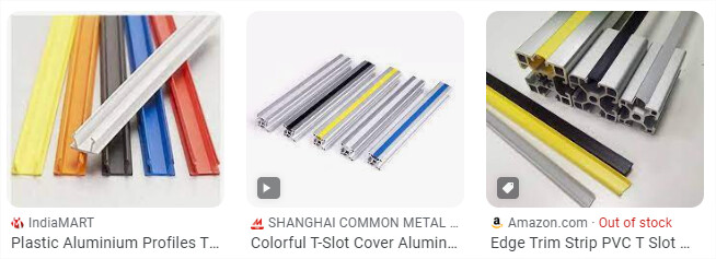
I suggest using these instead, as they allow to fit a lot more wires into the slots. They can be easily cut to size and they can be removed and put back super easily.
I use them on all my machines:

image

Actually for rigidity the best thing is really to have some rods at 45 degree. Adding one horizontal frame bar is better than nothing of course, but one rod placed at 45 degree would probably give ten times more rigidity. I wouldn’t add one at the front, for obvious ease of access reasons, but one at the rear would do the trick. The ideal being at least one on each plane.
That can also help slightly to adjust the frame squareness.

1 Like

Random ideas with orob today…

someone posted about using a zenxy for a laser. Cool. and I got to thinking about that a little. The only difference between the zenxy and a 3d printer (besides heaters and stuff) from a motion standpoint is that the printer has z motors and a cube while the zen could in theory have the same top end movement. Would it ever make sense to make a single setup for the top that could do either. I’m not saying you’d put a sand table on top of your 3d printer… but hey, there’s an idea i bet nobody tried before. but you could build a zen or build a zen and with the rest of the 3d printing hardware, make a printer out of it so it is 2 machines from the same bones.

does that make any sense or are the tolerances so much different between them that it is a stupid idea?

2 Likes

I thought about this too.

One problem is scale. the Zen isn’t designed to run particularly fast, though it can run a lot faster in the V2 version than the V1 would have ever managed. Using the conduit as rail works very well for the large size, but generally takes more room than the linear rail does.

Another issue is mounting the extruder. Again, the core of the ZenXY is larger than the car of a linear rail. It does have the CoreXY belt mounts integrated which helps, but when you add on an extruder (And probe and fans…) it gets unwieldy big.

On the flipside, MGN12 rail (or equivalent) in the kinds of sizes that we might want to make a ZenXY table is stupid expensive when compared to conduit and a few POM wheels.

2 Likes

The X Y Linear rails vs EMT is the biggest cost difference. in terms of size the Zen is focused on an optimized footprint to use as much area as possible.

3 Likes

Hot End / Extruder Width

So I need some basic dimensions to work with.

To work on the X rail I am going to need to know the widest extruder that will be in line with the X rail.

Currently, I think a Hemera is the widest extruder we use.

A hemera Xs is ~66mm wide,
An H2 is about 70 wide.
A Hemera regular is 78 wide.

So the question is Support Hemera and smaller or drop down to H2 and smaller?

Sorry I deleted all the previous stuff because it was too much info and I was not ready for it yet.

1 Like

They must’ve changed something in the matrix. I swear I posted a reply to this, but it has vanished.

V6 in a bowden configuration is probably the minimum. Though something like the E3D REVO micro might actually package just a bit smaller.

An H2 or hemera might be the largest for a single extruder.

But, it would be good to have a reasonable option for a dual bowden REVO Mini or dual orbiter direct drive.

Also, having acommodations to fit a EBB style CAN board on the carriage would be really great. This significantly simplifies and cleans up wiring to the carriage.

It would also be great to have an option for a rigid mount like the AlumiCore 2.0 that @niget2002 is fiddling around with

1 Like

Is best Bang for buck, but still reliable enough to trust based on forum experience (or broader printer community), Biqu H2?