Hoping to put a dent in the build tomorrow. I laminated 2 sheets of CDX ply together for a different build and was gonna repurpose it. The top surface is quite rough, though (it’s CDX, after all). Should I bother skinning it in MDF or just deck the CDX once it’s built?
Do folks tend to add a spoil board on top of a table, or do the ‘spoil board is the table top and you cut out the center of the spoil board once it’s built’?
For the MPCNC, I just made what was effectively a combination spoilboard/tabletop and then mounted the MPCNC onto it. I screwed a secondary sheet of 1/4" MDF onto that as a ‘more sacrificial’ spoilboard on top of that and ended up mostly using it like that for stuff I’d be cutting completely through.
So I wouldn’t worry about skinning it to start with, I’d just make it in the easiest way and then get cutting some stuff.
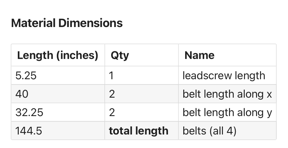
Getting started! Quick question on the belts: mine came as one continuous length. Should I cut it into these outputs from the calculator?
I ask because my last belt build was a CoreXY printer and I feel like those belt paths are a lil weird. Just making sure that I should be chopping this length up accordingly before doing so!
If it were me, I would build the gantry feed the belt through stuff and cut off the excess. Then do the same for each side of the y axis. No need to pre-cut into three pieces.
I’d figure out what you need and try to cut the belts ‘evenly’, ensuring that each belt is more than long enough. On the MPCNC there’s no harm to having excess and, indeed, I’d encourage it.
If you’ve got a single 180 inch belt and need 145 inches, I’d say that’s 35 inches extra or ~8 inches per belt.
So cut to 2x 49", 2x 41" in that case. You can always trim later. I just wrapped mine around the tube and cable tied it in place.
Same approach applies if you shrink the MPCNC, as well. I just pulled the belts out of the holders and moved them down, wrapping the excess up further. If I want to go back to a 600x600 that doesn’t need much in the way of cutting forces, like for engraving, plotting or running a laser, then I’m set.
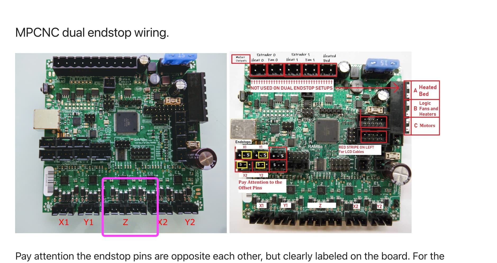
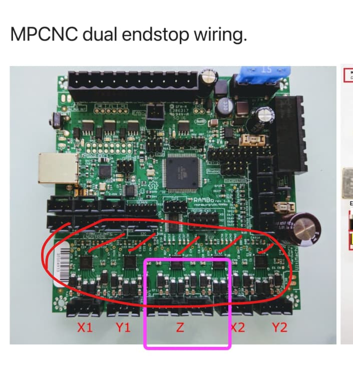
Also, is there a different wiring guide than this one? The fact that it is in the “archive” section makes me concerned that it’s out of date for some reason.
you only have 5 driver chips on that board. (red marks). The z has 2 plugs to the one z driver so you can run two motors for Z, which was a common “upgrade” for a 3d printer, but you won’t use the second z plug on this build. Just leave it open.
X1 vs X2 should not matter if matched by endstop and rotating the correct direction, but by convention, X1 is the minimum and X2 is the maximum. Generally speaking it is easier to sort out later if you follow convention. If you put them in the wrong place, and wire things backwards, I’ve seen people cut mirror images of what they wanted, so there is that possibility. User discretion is advised.
If you prefer having an attached screen then stick with what you have. If you had the mini rambo I would say for sure change it. The Jackpot 3 is a nice board and the user interface is much nicer and more CNC instead of 3d printer like the marlin boards are. I had a rambo on my LR2, then went to SKR on my LR3, and when the jackpot came out I switched over to that and never looked back.