Foam Cutter, how to control ESC

Hey, i have just finished building my MPCNC, and im looking to attach a foam cutter needle with a brush less motor and ESC Controlling it, does anybody know if theres a way to control the speed of the ESC using the ramps board output and gcode. instead of me attaching a servo tester inline and manually controlling the speed?


I know the ESC takes pulses, i thought about using the servo outputs, just unsure if this has been done somehow.

Cheers


Hi, I’m working on something that will do that in he future : a Foam Cutter Speed Controller.


It takes 2 inputs : a servo tester’s output, and rotation sensor (inductive sensor for now), and uses a PID loop to ensure a “constant” – that is once I’ve found the correct PID parameters-- running speed (like V1PID).

I plan on adding a third input (switched from the Servo tester) switch so that it can take the same outputs as done with the M3/M5 S (or O) parameters from the RAMPS, but I’ll need to see how to configure it.

I’ll probably have to check all configurations threads which concern the LASER/Spindle commands. One small hurdle is I see the LASER/Spindle option is conditional on not using servos, whereas I use one for ZHoming/Bed Levelling


There should be 3 modes at the end : pure Servo tester (or pot when I get one), PID from tester/pot, and command from RAMPS.


1 Like

This maybe helpful. I wrote this up after I was able to control my ESC:


My needle cutter: https://youtu.be/iOU6zelXMo8 has worked great for me since I ordered the hardware, printed the parts and assembled it about a year ago. I’ve been using the servo tester method to start and stop the needle, like most other people. But, I’ve always wanted it to be able to turn off and then end of a sheet of foam board. I’ve tried to figure it out myself without success. I’ve waited patiently for someone else to post how they successfully did it. Finally, I’ve figured it out and feel I need to help others because I’ve seen others with this same request in multiple locations. Here’s how I did it:


My setup:

MPCNC with a Needle cutter used for DTFB (purchased through V1Engineering)

RAMBO Board with Dual End Stops

Firmware Version: Marlin-MPCNC_Rambo_T8_16T_LCD_DualEndstop based on bugfix-2.0.x


Firmware Edit:

Uncomment line 2122 in Configuration.h and upload to RAMBO board.

From: //#define NUM_SERVOS 3 // Servo index starts with 0 for M280 command


To: #define NUM_SERVOS 1 // Servo index starts with 0 for M280 command


Hardware:

The V1Engineering’s discussion on laser’s, spindle speed, and pwm wasn’t working for me, but they gave me valuable clues.

https://www.v1engineering.com/forum/topic/laser-spindle-control/

https://www.v1engineering.com/mini-rambo-1-3/

I looked up the pinout locations for servos in the /src/pins/pins_RAMBO.h file. I didn’t change any of the pin callouts. The RAMBO board says:

//

// Servos

//

#define SERVO0_PIN 22 // Motor header MX1

#define SERVO1_PIN 23 // Motor header MX2

#define SERVO2_PIN 24 // Motor header MX3

#define SERVO3_PIN 5 // PWM header pin 5


I decided to use Servo 0 to connect to my ESC. Now, I searched for PIN 22 in the pinout schematic.

Pinout Schematic: https://github.com/ultimachine/RAMBo-1.4/blob/1.4/Project%20Outputs/Schematic%20Prints_RAMBo_1.4a.PDF


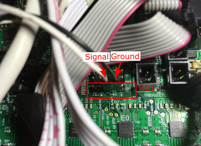
I had never really looked at these kind of schematics before, but deciphered that pin 22 was the middle of 5 pins on MX1.


So, I wired the ESC ground pin to the ground on MX1 and the signal pin on PIN 22 of MX1 (the middle pin on MX1). [My ESC main power leads are wired directly to the 12V mains].

[attachment file=108337]

Edited Gcode:

M280 instructions: http://marlinfw.org/docs/gcode/M280.html


Added this Gcode to my programs. I use Estlcam (which has worked great for me.)


At Program Start:


M280 P0 S040 ; Give low PWM signal for ESC to boot up

G04 S3 ; Pause 3 seconds for ESC to turn on

M280 P0 S080 ; PWM signal for Needle cutter. Change S<value> to required PWM signal


At Program End:


M400 ; Pause and wait for all moves to complete

M280 P0 S040 ; Turn off Needle Cutter
5 Likes

Ben,

This is awesome, and coming in the next few weeks i might be traveling the same path.

Which needle cutter did you use? The ones I found out on Thingiverse didn’t seem to have the new burly tool mount option which is why I designed my own contraption (which “works” and still tweaking).

I’m super excited to be able to just put the commands in the GCode and let 'er ride!

EDIT: Just watched your video of it cutting and it looks great. I have to ask, why you went with a longer needle and having the MIG tip so high up. I was planning on zeroing the mig tip to the top of the foam and have about 5.5mm of wire travel to get just through the back paper. Your cut seems very clean but also seems like the wire was flexing here and there.

1 Like

Please forgive my noobness, but I have two questions:
-Why do you need to control the speed for foam cutting? Can’t you just set it to full speed and let it cut? That would impact the cut quality?
-Why don’t you just use the bed heater or the extruder heating element ports of the machine? That would make it very easy to interface, you’d just set a temperature and it would correlate to a speed without having to code anything. All the Gcodes already exist for temp control.

1 Like

I’m not up to speed on the latest MPCNC designs, but this is the needle cutter I used https://www.thingiverse.com/thing:2450613.

The needle depth, travel speed, motor rpm’s can all be adjusted to get the desired effect. I think I remember others suggesting 6 or 7mm depth of cut. I find that 7mm depth of cut works for me. It allows the pieces to stay together, but can easily be separated. I think your idea of lowering the MIG tip will make the setup work better. I didn’t take the time to do that because what I stumbled across worked for my needs.

Running at full speed causes everything to get quite hot, which is not great for some of the PLA components. I don’t use the extruder heating element because I’m using a hobby ESC to run the brushless motor, which requires a PWM signal.