MicroUSB Drivers, still a voltage drop (.4v?) but not bad.
P.S. I accidentally unplugged a driver while it was powered up and heard a little snap. Just tested the board and drivers with steppers and it all seems functional still!!! How cool is that. No promises that ever doesn’t kill something again.
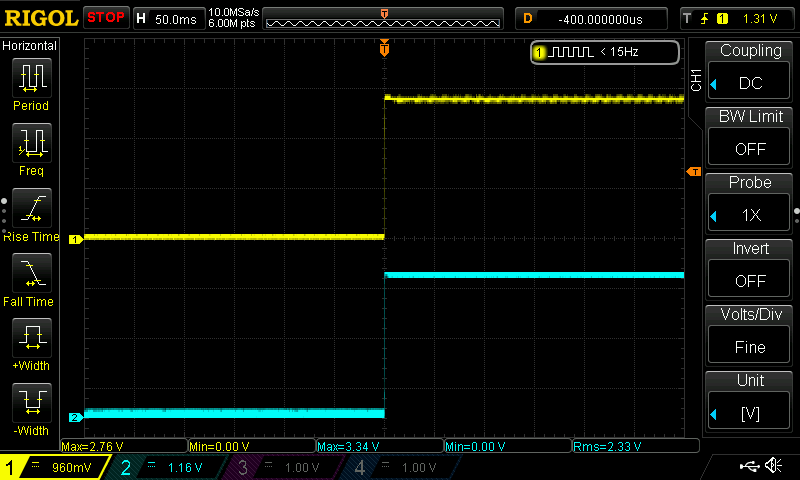
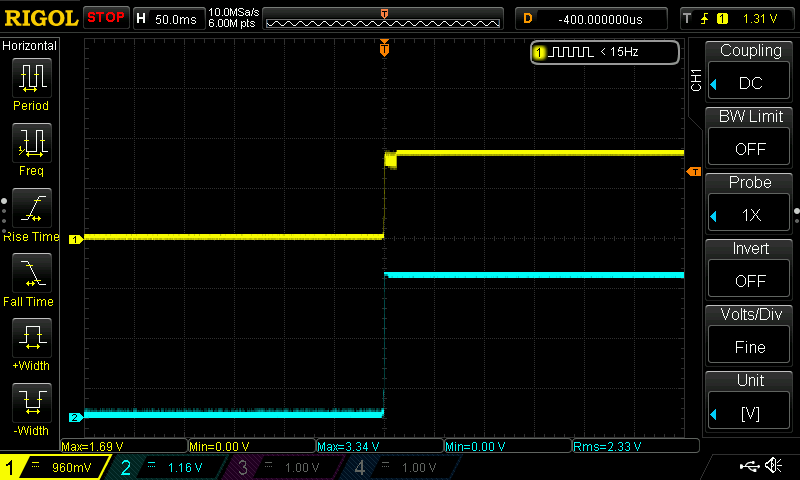
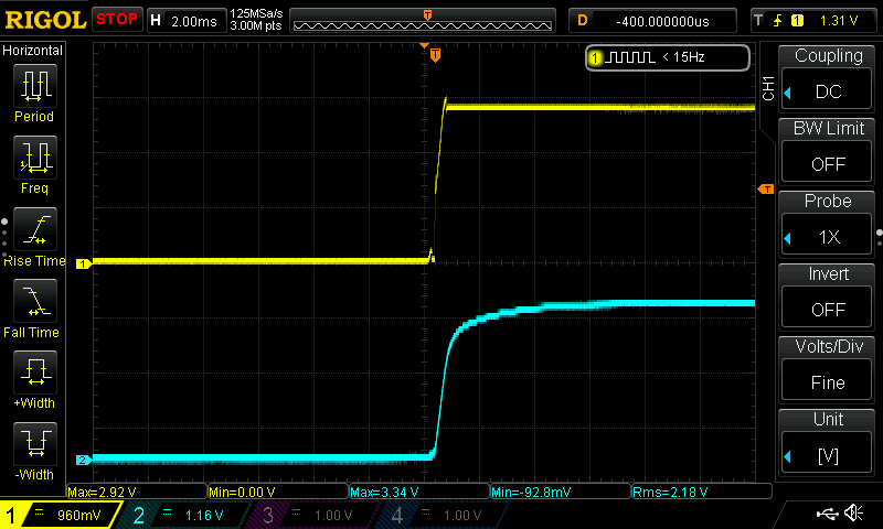
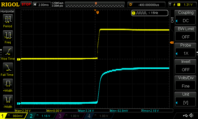
For completeness, what happens if you repeat the setup with USB-C, drivers installed, and USB-C cable connected to a host. Then hit reset a bunch of times and grab any reset after the first one.
I’m curious if the levels are different. I bet they are.
Edit to add: One thing I’ll be doing with one of these that I order from you will be mucking about with that resistor.
Edit 2 (Yell at me if this gets tedious )
What if… Bart is on to something… Why did the ABC stepper drivers need to be behind that funky serial mux? What if, as you add drivers, there’s a cumulative impact that makes this problem worse?
I note that if you draw in the 3v3 pullup on the boot pin inside the ESP32, and added the UARTS on the TMC 2209s, you’d find that while the 2209s aren’t enabled they’re sinking current on those UART pins, acting as a pulldown. The more you have, the more the effect. If your ESP32 has a weak 3v3 power supply and/or a crappy pullup resistor value… no boot. The more drivers you have in parallel, the worse this problem becomes.
The series resistor in the jackpot then is an attempt to kludge that by limiting the pulldown effect while still leaving sufficient drive for the UARTs to work when not at boot time and the BOOT0 GPIO is back to being a UART pin?
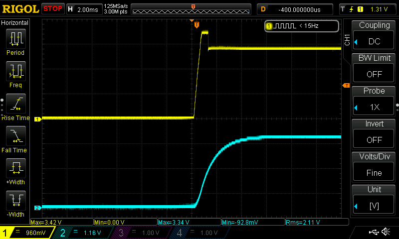
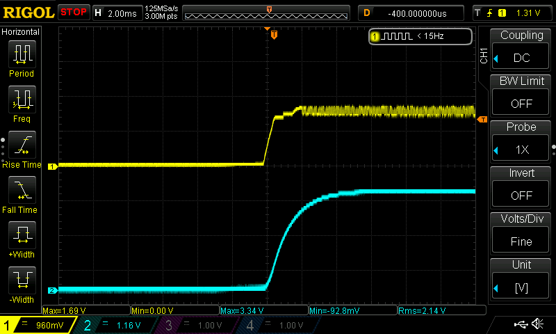
That explains it. It just doesn’t explain why it works when fluid term is connected for Keith. I was expecting to see something temporary from the drivers and then have it normalize back above 2.5V.
It doesn’t really matter though, if this fixes it.
I would really rather see that boot pin up much closer to 3.3V. But I haven’t probed those pins. Maybe I flirt with disaster all the time and I never look closely enough.
Can you make the resistor between pin 0 and ST_UART on the JP bigger, so it pulls it down less?
We discovered it did NOT need to be fluidterm. I could get a successful boot when:
Connected to the Macbook Pro and fluidterm.sh is executed.
Connected to a USB battery and RST is pressed.
Connected to iPad Pro with 51% charge and RST is pressed.
It did not boot successfully when:
Connected to the iPad Pro in low power mode due to depleted battery (20%) (with RST)
Connected to the USB battery but off. The connection never drew enough power to trigger the battery to enter charge mode. I had to press a button to get it to turn on. I tested it before presssing that button and RST did not work.
Occassionally I had to press it twice, I thought it was a time related function, but perhaps it was just noise, and whether the pin crossed the threshold or not.
The weird one for me is I don’t recall the RST button working when plugged into the Macbook Pro. I set this one aside, because I stopped trying the RST button more than a week ago, and I truly don’t remember if I rigorously tested pressing RST after connecting the MBP.
At the time I was testing the theory that the connection was acting as an antennae. Once I understood the role of the drivers, I tested the USB battery and the iPad Pro (wish I had tested the MBP at that time, but I was trying to exclude anything that might happen with connection of terminal, connection at the serial port, or fluidterm, so I didn’t.)
I have some genuine boards on the way. I had previously asked about a few fixes to make it work with cruddy ESP’s. When those boards get here I would love to hear all the ideas on possible fixes and I can test them on a slew of esp’s I have on hand. I just want to make sure we do not knock out the ability to use genuine boards as well…Or just solidify the need to use only genuine.
We have a report of a microusb version doing this same thing, with a 1k pullup as a fix.
I also did not think to look at it with the USB to help it boot. I still have it all setup and I can do that tomorrow, or maybe this evening. I enjoy getting real answers and seeing it on the scope.
I tried spamming the rst button to see if I could get it to work. I tried both buttons. It is a weird problem. I am very very excited to see how a genuine esp behaves. These cheap boards might be way worse than we expect. Like Heffe said, I expected the voltage to fully recover after boot and it doesn’t even on a good board, that seems very odd to me even though we have plenty of power. So maybe there is a power supply issue. I guess I can put a meter or probe on the 3.3V rail as well to see if that is it.
Now that Ryan has a way to reproduce it, it is really back in his hands. We have a couple of decent fixes, but it may be a new version of the JP board needed, or another resistor added to fix it. That won’t be very quick. You should get on with your machine until we need a fix tested, or we have a solid solution.
I just used my last esp32 putting wled on the LR3. I could always use a few more laying around as long as they will work for other things. Thinking of making some scales to put under my filament dry boxes to know when they are getting low lol. Have everything but the controllers at home. Said all that to say I will buy a few if you want to move them. Shoot me a price lol
I’m working on a full hardware rebuild and there’s a workaround - just plug it in to a laptop when I first turn it on - so it’s not really impinging on my workflow, such as it is.
I’m also not short on electronics projects, so I’m also interested in more assorted ESP32s if it helps recoup some of your costs.