ATmega 328P have internal resistors. They are software enabled/disabled, a bit non-linear, act like a 30K to 40K ohm resistor, and (according to a few guesses by people better educated in electronics than I am), likely implemented using transistors. It is almost certain these resistors are enabled for the endstop circuit rather than leaving the pin floating.
Interesting to read all your explain information about switches, grbl firmware and codes. Thank you @ttraband for beautiful helpful.
I learned little bit GRBL Firmware, last time I was used it to test stepper motors with Vref Voltage, I will learn more GRBL Firmware after done step up with switches.
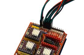
I found pictures that I can following to connection switches without Parallels and Series?
See pictures at below
The pins on the shield are in parallel. Both Z+ and Z- on the shield connect to the same pin on the underlying Arduino Uno, and the same is true for X+/X- and Y+/Y-. You can check this with a meter or test light - the + and - pins on the each axis are the same. The shield makes it easy to connect 6 switches, but there are only 3 signal pins.
If you wire the switches as diagrammed, I don’t think (I haven’t tested it myself) that any of the axes will ever read as “triggered” unless both switches for the axis are pressed, which is, shall we say, mechanically unlikely in normal practice.
You can get away with NO switches in parallel, but multiple NC switches need to be in series. The feature list on the Protoneer web site for the CNC shield states
Limit switch pins have been doubled up so that each axis has a “Top/+” and “Bottom/-“. This makes it easier to install two limit switches for each axis. (For use with a normally open switch)
Check out Wiring Limit Switches for diagrams similar to those you provided showing NO and NC options. The CNC shield v3.00 connects X limit pins to Arduino pin 9, Y limit pins to Arduino pin 10, and Z limit pins to Arduino pin 12 by default. The Z limit pins gets swapped with Spindle Enable (pin 11) on grbl versions 9.0 or later when the variable spindle option is enabled in config.h. Later versions of the cnc shield (3.10, I believe) have been updated to reflect this change, but you can use the older shield as long as you understand the pin change. The cnc shields available inexpensively online all seem to be v3.00, as far as I can see.
2 Likes
The newer versions haven’t been copied in China yet not sure why may be no longer opensource?
Or someone got a million boards made and hasn’t run out of stock yet.
There are loads of posts in various forums saying “you can’t use the old shield with the new grbl” but the electrons running through the board don’t care what the silkscreen on top says.
With a little tweaking in config.h I’ve got a v3.00 shield running:
- 3 axes
- 3 endstops (hard and soft limits now that the capacitors have cleared out the noise)
- 1 probe connection (also relying on a capacitor)
- Variable speed (PWM) spindle control (no reverse, but the DW660 only runs one direction anyway)
- 2 individual relays for “flood” and “mist” coolant control (eventual vacuum hold-down and possible air blast for chip removal)
- 3 grbl “special” buttons (cycle start, pause, cancel)
Since I’ve got mains voltage running to the relays, I’ve got a ‘real’ e-stop that cuts all power to everything on the machine rather than wiring in the grbl e-stop/arduino reset, but I’ve got no doubt that it would work if I added the switch to the pins.
I could switch to a ramps board or one of @buildlog’s new modular grbl cnc controllers to get the additional drivers and endstop pins to support auto-squaring but I had the CNC shield in the spare parts box, and its doing all I ask of it so far.
2 Likes
This is my understanding too. I would hope they are enabled, but there are good reasons to disable them sometimes too (if you were switching between 5V and floating, you would want a pull down) so I’m not 100% sure.
It’s also common to just put them on the board between the micro and the header. I haven’t seen the grbl shield recently enough to tell you.
Regardless, the capacitor is working in a similar way, so good fix.
Yes I think they get the pin 12 (pwm)? switch confused and think it won’t work but I haven’t had trouble either. I use one all the time but haven’t used PWM
I understand clear what you explain, Can I following this switches wiring for my CNC Shields from this link?
What is difference between NC and NO?
Which is better or Which I can use NO or NC for CNC shields?
Normally Open (NO) means that the switch is disconnected and when you home the machine, the switch complets the circuit. Normally Closed (NC) means that the switch is connected and when you home the machine, the circuit is disconnected. NC is a bit better in case of a failure like a wire coming lose or breaking. If you try to home in an NC setup with a broken wire, the stepper just doesn’t move. In an NO setup, the stepper with try to drive past the endstop position until you cut the power.
@ttraband has the clearest description of what you should do:
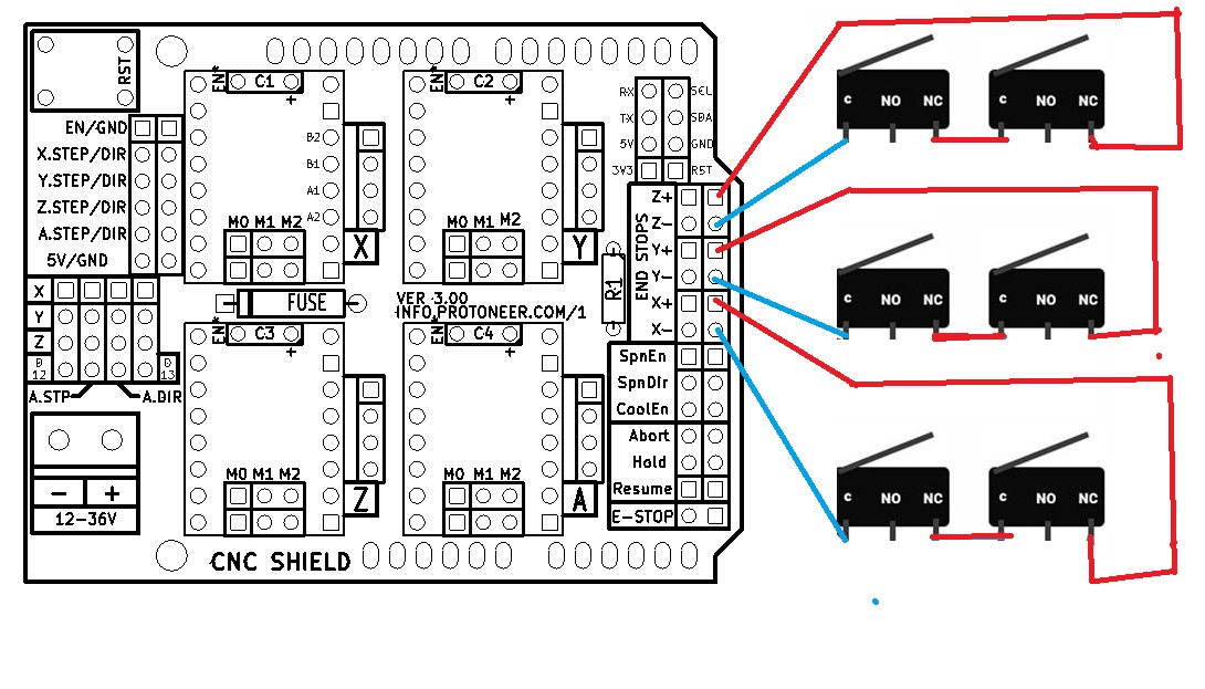
If you’re doing 2 NC limit switches on a single axis, you’d only use 1 of the CNC shield pins and have the two NC switches wired in series, and use $5=1. Tripping either switch opens the circuit. I’ll go back and edit my post to make this clearer.
That is, you will only be using one plug on the CNC shield for each pair of switches instead of two. Note you can run the pair of wires for each switch to the CNC Shield and make the series connection at the CNC shield with just a jumper between one of the wires on each switch. No need for anything complex. I got to run or I’d do a quick drawing for you.
1 Like
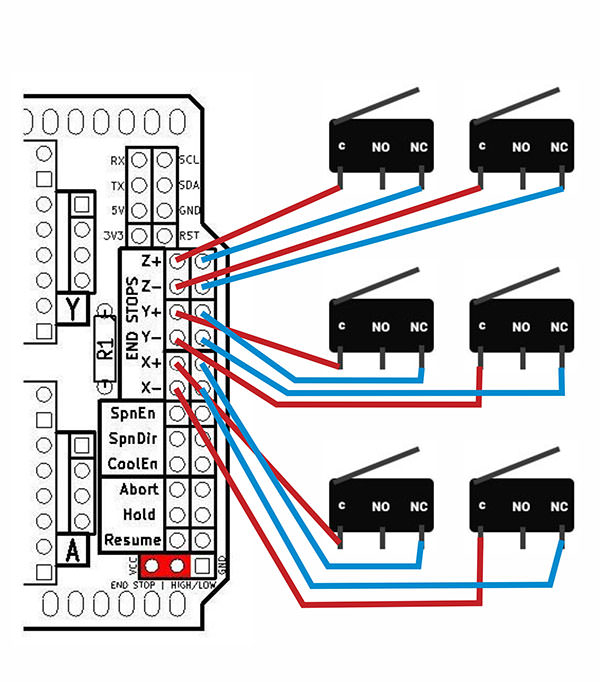
I tired drawing on picture of NC switches wiring in series diagram in MS Paint. I wonder this connection is correct?
1 Like
Yes, this is a correct wiring. There is no polarity to these switches, so things can be swapped around and still work. As one example, you can tie the NC from both switches together and then use the C wires from both switches to plug into the CNC Shield. From a practical point, it is probably easier to make this wiring connection at your CNC Shield. So imagine you have a red and blue wire pair coming from each end stop to the board. Taking the two switches for one axis, a red wire of one switch gets tied directly to a blue wire of the other switch. The other red/blue pair (one from each switch) gets plugged into the board…and it doesn’t matter in what order. This wiring at the board is the same circuit you have in your diagram, but with a longer wire run.
1 Like
I already install wiring for switches, I will test it at later and I will let you know soon.
Thank you for help
Sorry, I was out of contact for a few days. That latest diagram looks fine to me, and I agrew with @robertbu’s comments as well.
Good luck!
1 Like
Hard limit $21 = 1 is work and switches is work but I got problem , when roller hit switch and stop but it refused to move back same position
GRBL Command error: “An unexpected error was detected: ALARM: Hard limit”
Do I need a noise filter, like I add resistor and capacitor?
That’s how hard limits work in grbl. When (except during the homing cycle) a limit switch is triggered the machine is immediately stopped to protect it from damage, the controll software is put in an ALERT state, and requires operator intervention to unlock the machine again before the motors will move it.
As long as you aren’t getting alerts when the switches aren’t physically triggered you shouldn’t need noise filtering. Some of my NO limit switches suffered from “phantom” hard limit trips, which is why I needed to add the filtering capacitors.
All the relevant parameters for grbl are explained at the Grbl v1.1 Configuration page. Some sites seems to imply that you need hard limits ($21=1) and soft limits ($20=1) enabled for homing ($22=1) to work properly, but that has not been my experience. I have had the homing cycle work with both those parameters set to 0 as long as:
- Physical limit switches are installed and wired to the control board - at least 1 per axis you want to home.
- $5 matches the way the switches are wired ($5=1 for NC switches)
- $23 is set to match homing toward where the switches are physically installed.
- Config.h is set to match the axes you want to have participate in homing. (I don’t currently have a Z limit switch in place, so I’ve disabled Z homing in config.h.)
During the homing cycle, each axis will move in the direction specified by $23 at the homing seek speed specified by $25 until the switch is triggered, back off and trigger the switch again at the (lower) homing feed speed specified by $24, set the machine’s origin point as specified in config.h (default is putting the machine coordinates in “negative space”), then finally moves the distance specified in the $27 configuration parameter. Make sure you set $27 large enough to deactivate the hard limit switch.
I do like using soft limits, but they only make sense if you set appropriate max travel distances with $130 (for X), $131 (for Y), and $132 (for Z). These are easy to set once you can use the machine control software to find the travel limits relative to the hard limit switches.