Dual End Stop Ramps 1.4 Wiring help

Motor X1 must be matched to endstop x-min, and motor X2 must be matched to x-max. In homing, the motors are driven independently, so the X1 motor will stop when the endstop on that end is triggered. This allow the two ends to square themselves against the endstops. This is the primary benefit of endstops. Once you get your rig setup, you can test this by moving an axis out of square and then running the homing sequence. You will see one motor stop before the other.

1 Like

So for dual endstops, you use 5 drivers for 5 motors. On a RAMPS type board, these are typically labelled X, Y, Z, E0, E1. For purposes of 3D printing, they are for the X, Y and Z axes, as well as 2 extruders, (E0 and E1)

The V1 MPCNC firmware for these renumbers them, and they are instead used as X1, Y1, Z, X2, Y2, but X2 and Y2 will still be laballed as E0 and E1 on the actual board.

1 Like

Thank you all, i’m a lot more confident to power up the board after your help and clarifications. One last question, I see the point of having the X1, X2 etc paired in a specific way, but… does it matter if in my setup X1 or Y1 is the left or the right motor of that axis? I guess that as long as it goes to the correct end stop i.e. the end stop on the same truck as the motor and the pairing is according to what @robertbu said, motor placement shouldn’t matter, am i right?

1 Like

That is correct. As long as the endstop is matched with the motor, it doesn’t matter which is which side.

For ease of troubleshooting, I set mine up so that X1 and Y1 are the motors on nearest the origin of the machine, that is to say that the X1 motor lives on the rail closest to minimum Y and the Y1 motor lives on the rail closest to minimum X

2 Likes

It will matter if you adjust the squareness with software. M666 will let you add an offset, so one motor will jump away from the endstop a bit more after homing. It is useful if your physical endstops aren’t perfectly aligned with square. But if you do M666 X0.5 and that moves it the wrong way, you can do M666 X-0.5. So not a huge problem.

1 Like

Everything seems to work just fine! I performed all the checks mentioned In dual end stop section and they pass, so once more thank you for your help!

One thing I noticed though is that with the new firmware, after homing, I cannot move either X or Y pass 200. Before homing I can take them all the way to the other end but once I home X and Y, 200 seems to be my limit. Any idea why?

Also is there a way that I can “hardcode” my firmware so that it homes after every reboot automatically and it also knows the max distance it can travel on X and Y after homing?

If you are limited to 200, then you don’t have the latest firmware installed. The latest firmware sets the limit at 600 instead. The two lines in configuration.h that set this limit are:

// The size of the print bed
#define X_BED_SIZE 600
#define Y_BED_SIZE 600

Unfortunately thse values cannot be set by g-code and would need to be modified in configuration.h to match your working size and Marlin recompiled and reflashed.

Also, the defaults in the firmware don’t limit the max. So something is funny. You can see what version you have with M115.

19:02:27.058 : FIRMWARE_NAME:Marlin 510D 2.0.7.2 (Apr 29 2021 23:29:13) SOURCE_CODE_URL:GitHub - MarlinFirmware/Marlin: Marlin is an optimized firmware for RepRap 3D printers based on the Arduino platform. Many commercial 3D printers come with Marlin installed. Check with your vendor if you need source code for your specific machine. PROTOCOL_VERSION:1.0 MACHINE_TYPE:V1CNC 510D EXTRUDER_COUNT:0 UUID:cede2a2f-41a2-4748-9b12-c55c62f367ff

This is what i also see in the Configuration.h file

// The size of the print bed
#define X_BED_SIZE 600
#define Y_BED_SIZE 600

even when i changed it to 1600 for both it didn’t move any longer, 200 was the max i could move both axis

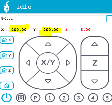
Again, after homing X and Y i can only go up to 200

image

For what its worth… i also have this in my config file
#define DEFAULT_AXIS_STEPS_PER_UNIT { 160, 160, 800, 160 }
(5mm x 5mm square will size 6,2mm x 6,2mm)

I don’t use Repetier-Host, but I assume the issue is with how you’ve setup your printer in Repetier-Host. In Repeteir-Host, go to Config/Printer Settings, and click on the Printer Shape tab. Set the X Max and Y Max values here to the size of your MPCNC.

As or the 5mm being 6.2mm, that can happen for a number of reasons, but with the specific amount your are off, most of the time it is because you use a 16t pully instead of a 20t pully on the steppers.

2 Likes

Thank you once more! I’m able to move pass 200 manually from the knob on MPCNC screen. So it must be something on Repetier.host that limits to 200; I’ll deal with it later.

Regarding this:
define DEFAULT_AXIS_STEPS_PER_UNIT { 160, 160, 800, 160 }
(5mm x 5mm square will size 6,2mm x 6,2mm)
it was me who had this problem when I was not using the dual end stops and this config change, solved my problem; so i altered it in the dual end stop firmware again. I haven’t made any accuracy tests but hopefully i will soon…

I think there is a bed size in RH. Maybe there is also a checkbox that says, “mind your own business, repetier and let me move where I want”.

If you have a 20 tooth pulley, it will need 20% fewer steps/mm. It will also give you 20% less torque. But it should work fine. Next time you make a slow boat order from China, get the 16T pulleys and you’ll be fine.

After 2 attempts to fix this issue I gave up and come back to the experts… This is the firmware i have v510 2.0.7.2 and these are the values i have in my configuration.h

#define X_BED_SIZE 335
#define Y_BED_SIZE 410

Still when i move on X and Y axis, manually from the screen knob, i can get pass 335 and 410. So indeed something is funny. Unless the limits i set in the config file are in different scale to what i see in the screen.

Any help will be as always highly appreciated…

Limiting the maximum travel in software is called software endstops or soft stops. In order for soft stops to work 1) the machine would need to be homed before attempting maximum movement, and 2) softstops would need to be enabled in the firmware. By default, they are not enabled in the firmware maintained by V1. Since most CNC work is done relative to the workpiece (i.e. the origion for a job is some point on the stock), soft stops have little use on a MPCNC. If you want to enable them, this define would need to be uncommented in configuration.h:

//#define MAX_SOFTWARE_ENDSTOPS

The original problem I thought you had also uses the bed size values. If you attempt to home your machine from a distance greater than the bed size values, your machine will stop and produce an error. In previous versions of the software the default bed size was set at 200 x 200, so if the router was more than 200mm from from home on either axis, homing would fail. This was increased to 600 x 600 in the latest version of the MPCNC maintained firmware. I misunderstood your original issue, and it was a Repetier-Host setup issue, not an issue of bed size in the firmware.

1 Like

If it works from the controller and you’re getting all the motion you expect, then I seriously doubt that there’s a problem in the firmware configuration.

If it works from the controller screen but not from within Repetier host, check the Printer Settings in Repetier as @robertbu suggest to make sure they match your actual machine.

2 Likes

The only thing I haven’t done yet is to uncomment the line above and I understand this is why I can pass the max limits defined in the configuration.h file after homing, where I shouldn’t. I’ll try to rebuild and upload today and see if indeed this will work for me. On the other hand, in my controller’s screen I see in the motion menu that soft switches are ON. I guess this is something different to the max values, maybe it is the dual end stops (?)

Br,

It is probably on or off for all of them and only the min is enabled.

For most MPCNC users, getting the soft stops to work provides zero value. Say you home your machine and then navigate to the origin/home point on your stock. From the g-code point of view you need that stock home/orgin point to be at coordinates (0,0,0), so you execute a G92 X0 Y0 Z0 either manually or at the top of your g-code file. But after executing this command, Marlin no longer considers itself homed and therefore soft stops are not active. So the place you really would like softstops to work is during milling, but they are disabled by the G92.

There are a couple of exceptions. First, if you were to create a couple of fences on your spoil board so that when you mounted your stock the orgin/home of the stock and the home of the machine were the same point, then there would be no need for a G92 and therefore soft stops would still be enabled. I’ve read just one topic where one MPCNC user setup his machine this way. And to make it work, it restricts the home/origin of the stock to the corner. I frequently use the center top of the stock as my stock home/origin. The second exception is using workspaces. Marlin has the ability to do milling in a different workspace than the physical machine workspace. This would leave soft stops enabled. Workspaces have been talked about on this forum as a conceptual solution to some problems, but I have not seen on the forum anyone that is using them with Marlin.

Note the above is not to discourage you from getting soft stops working. I just wanted to set your expectations for the benefits of soft stops.

2 Likes