Then all I can say is, good luck.
We’ve provided other options for at least the CAM portion through the use of exporting to DXF, but if your plan is to stick with SW, then I hope the VARs can come up with a good solution for you.
Then all I can say is, good luck.
We’ve provided other options for at least the CAM portion through the use of exporting to DXF, but if your plan is to stick with SW, then I hope the VARs can come up with a good solution for you.
Thanks.
Value Added Reseller or basically in the CAD world your drug dealer and you are his junky.
They are also the guys in the middle of the pyramid scheme… They pay some licensing fee to the CAD developer, and develop the add-ons and useful widgets that the core developer doesn’t want to be bothered with, yet. Usually with a clause that they can basically co-opt anything really useful and merge it into their codebase. This is pretty rare, though, since having the VARs handle that stuff means they also handle the support (which is often a shrug and complaint that they aren’t getting support from the developers).
Everybody wins!
Except the users, of course.
Precisely. I find the entire VAR system to be very archaic and almost fraudulent in some respects (like your pyramid).
Yes, I had to google it to understand the manufacturing tools end of things and then into a rabbit hole. I knew that such existed from a grade school chum of mine who became a lawyer. He also played in programming and did some stuff for his law firm in accounting. Some voodo magic coding and he got some type of VAR for SAP and sold his code and retired to a farm at the age of 50.
I like this story of subverting the game:
Nothing different than the fights between the Medieval guilds and any new technology or knowledge.
I bought it when my wait got over a minute. IGoing from Inkscape to EstlCAM for simple surface stuff isn’t bad at all. But I wanted to mill some curved slots in the tops of my slip fit boxes to make a finger hold for pulling them apart. Threw the STL in and it crabbed at me.
Played around with in in KiriMoto since I drew it up in Onshape too. Now I have to study how does one mill this part in one setup and with what bits or do I just make is a square pocket. It’s a dead simple part to make in Inkscape and to do the CAM in EstlCAM. But just adding that curve changes everything.
Looking at this made me realize that back in the day, one of your machining projects in high school would be to make an ashtray for your dad. Ha.
Made a breakthrough tonight/this morning as I found the CALL command and it allows argument passing. Too tired to proceed but this part would handle a sub piece I need though the main piece I am still stuck at. In time…
Well, I figured out what that VAR did wrong by piecing the parts together. Seems when you print ANY decimal number it converts that decimal to metric so everything is 25.4 times more. To get around that you have to put a directive (N) in the formatting part.
edit: Here is one for you that the .pdf never mentions but a CALL with arguments needs 1 more than what you will use or it locks up. This is how bad this is but anyone with a programming background can see how bad this is via the pdf I uploaded.
But have any ever actually added any value? They constantly call you, trying to sell you more software or support that you don’t need and can’t get you the answers you need when you have questions. That’s my primary experience with the majority of VAR’s in the software world. Not sure how things are in the other industries.
I think I’ve worked with that developer before. He would argue that he was much smarter than me and that he didn’t make mistakes and I must be QA’ing the software wrong. Those were good times.
I finally got it to work. YES, it works.
Here is something from the manual - Parameters must be defined as MODAL parameters in order for this command to have any effect. WRONG, it MUST be set MODAL or it will lock up.
I haven’t really delved into the G99/G98 part but here is the canned cycle uncanned
MCALL CYCLE83 G99 -15.00 Z-12.00 Z-33.60 Q.40 F917.96
G0 Z-12.00 F917.96
M8
;Simulate Peck Drilling G83
G1 Z-15.40
G0 Z-12.00
G1 Z-15.80
G0 Z-12.00
G1 Z-16.20
G0 Z-12.00
G1 Z-16.60
G0 Z-12.00
G1 Z-17.00
G0 Z-12.00
G1 Z-17.40
G0 Z-12.00
G1 Z-17.80
G0 Z-12.00
G1 Z-18.20
G0 Z-12.00
G1 Z-18.60
G0 Z-12.00
G1 Z-19.00
G0 Z-12.00
G1 Z-19.40
G0 Z-12.00
G1 Z-19.80
G0 Z-12.00
G1 Z-20.20
G0 Z-12.00
G1 Z-20.60
G0 Z-12.00
G1 Z-21.00
G0 Z-12.00
G1 Z-21.40
G0 Z-12.00
G1 Z-21.80
G0 Z-12.00
G1 Z-22.20
G0 Z-12.00
G1 Z-22.60
G0 Z-12.00
G1 Z-23.00
G0 Z-12.00
G1 Z-23.40
G0 Z-12.00
G1 Z-23.80
G0 Z-12.00
G1 Z-24.20
G0 Z-12.00
G1 Z-24.60
G0 Z-12.00
G1 Z-25.00
G0 Z-12.00
G1 Z-25.40
G0 Z-12.00
G1 Z-25.80
G0 Z-12.00
G1 Z-26.20
G0 Z-12.00
G1 Z-26.60
G0 Z-12.00
G1 Z-27.00
G0 Z-12.00
G1 Z-27.40
G0 Z-12.00
G1 Z-27.80
G0 Z-12.00
G1 Z-28.20
G0 Z-12.00
G1 Z-28.60
G0 Z-12.00
G1 Z-29.00
G0 Z-12.00
G1 Z-29.40
G0 Z-12.00
G1 Z-29.80
G0 Z-12.00
G1 Z-30.20
G0 Z-12.00
G1 Z-30.60
G0 Z-12.00
G1 Z-31.00
G0 Z-12.00
G1 Z-31.40
G0 Z-12.00
G1 Z-31.80
G0 Z-12.00
G1 Z-32.20
G0 Z-12.00
G1 Z-32.60
G0 Z-12.00
G1 Z-33.00
G0 Z-12.00
G1 Z-33.40
G0 Z-12.00
G1 Z-33.60
G4 P500
;Simulation done
G0 Z25.00 F917.96
Well, this language is like cobol, c, and basic all thrown together but the best stuff from each was left out. The manual is barely adequate and don’t believe what it says just use it as a basis to try something yourself.
All of this is to make us dependent on those VARs and, as you said, they never really bring any value to the table.
Awesome work, man!
You might want to cap the feed rates on the z. Are the individual axis rates available to the pp or are trig functions available? I don’t see any harm in going ahead and adding the feed rate to each movement command just to be safe.
…oh wait, probably wouldn’t need trig, just xyz vector math and a square root function.
The speed can be set in the cam program but being ignorant about the cam portion still it is all gibberish to me. Now knowing Marlin the way that I do I have this forcing Marlin to max settings to be safe. For instance my Z can’t handle more than 3mm/s on my CoreXY and when I switched to 2.0 they had neutered the max settings but thanks to a few requests we managed to get them to bring that back.
This G98 and G99 I will do later as it will require a lot more work but G98 is what I showed above so that works.
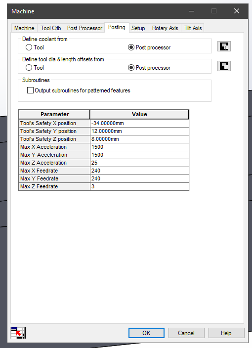
;Marlin Based Gcode
M201 X1500 Y1500 Z25
M203 X240 Y240 Z3
This was the first thing I did.
It looks like your example peck operation is running at 918mm/min => 15 mm/s, no?
Yes, 917.xx and that I saw on the bit info. Of course the M20x commands have Z hard set to 3mm/s in the above example.
To change that speed I would have to go into the library to mess with that or tell it Defined by Operation and I can change that Z Feedrate that way (much better that way I think).
Cool. Though it might be something to circle back to if you plan to share your pp.
Oh, I am sharing this PP for sure.
I am not understanding G99 at all.
Here is G99
N308 G1 Z-15.4 F917.963
N309 G0 Z-12.
N310 Z-12.4
N311 G1 Z-15.8
N312 G0 Z-12.
N313 Z-12.8
N314 G1 Z-16.2
N315 G0 Z-12.
N316 Z-13.2
N317 G1 Z-16.6
N318 G0 Z-12.
N319 Z-13.6
Here is G98
G1 Z-15.400
G0 Z-12.000
G1 Z-15.800
G0 Z-12.000
G1 Z-16.200
G0 Z-12.000
G1 Z-16.600
G0 Z-12.000
What is the G99 doing as it seems crazy to me? Looks to me like G98 goes all the way back to the starting point each time whereas G99 only goes back the same amount each time then goes back to the starting point so crazy.


