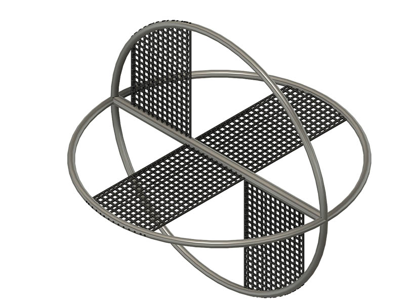
After ordering 100 feet of 22-gauge SS 316 wire, I might not need it after all. Think I might use that SS mesh I bought for the top instead and cut and bend it like shown in this photo since I don’t seem to need that. The 1.5” width center mesh will move it away from the heat and the outer blades will move it back in. I might put some painter’s tape on there first to see if it does what I think it will with some beans added.
I also took that one bad B&D electric screwdriver apart and took it a little too far apart. Apparently that driver had about an 80:1 gear reduction in it as that little motor is spinning probably 10,000 RPM or better. I kind of like these stand-alone motors for starting out with this project, so I ordered a JGY-370 12V 210rpm motor today. Most things I use that portable PS with are 12v which is why I chose that over 6v.
[Edit] I would recommend just looking at the video in the next post as it shows 3 methods & is a shorter video.
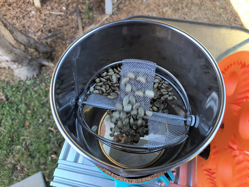
I did 2 different tests with the mixing of the beans today using painter’s tape as a mockup. The 2nd one which seems to mix the best to me is like the image shown in previous post. The 1st test has the tape all the way across on the sides like center is. I might should have done one more test with the center tape only on one side like the outside tapes.
I want to bend the inner agitators inward a little more since they are still scraping the bottom a little. Seems like over time the SS mesh or wire might wear out that screen and it does not really need to touch for my use.
I went ahead and did the 3rd method before it gets cold again tomorrow. Now I think the 3rd method is better. I made each method about 20 seconds long but made the 3rd method just a little longer.
I am a little slower going when it comes to the electronics but made a lot of progress with it now. I finally realized that I had an easy way to run the nema17 motor as the drive motor using a CNC shield. The shield is from Zyltech as well as the motors. I only need 1 of the 4 motor drivers but it does simplify the wiring a lot and think I have enough extra pins to do what I need. I don’t know why I was so reluctant to use the stepper motors. Like one or more folks have said before, the Nema lets me go any speed. I just found probably a better board for this, an Arduino Nano CNC shield with only 3 motor drivers. Smaller footprint and more pins I can use. Here is the one I found: https://www.aliexpress.us/item/3256809781787705.html It does have a different connection type for 12v than Arduino uno CNC shield has. The one I am using now is working fine, but just in case I run out pins.
I incorporated the pushbutton part of a joystick to change the RPM of the motor and a long click to stop or start it. I only have the button for it wired up for now. I got some SS 304 20 mesh to cut for the agitator baffles. The 8 mesh I had seems like it might be a little too difficult to bend.
I initially used a pancake size nema17 which is rated at 0.12 Nm and is probably sufficient. It was just warm to the touch after running for 10 minutes with no beans. I decided to switch to a 0.42Nm normal size nema17 as the extra weight is not really a concern to me, but the torque might be. It does not even get warm. Here are the speeds I currently have programmed into the Arduino. 180rpm is what the B&D battery powered screwdriver was running.
Motor → Drum RPM (0.9° motor, 1/8-step; gear = motor ÷ ratio)
Motor RPM
Drum @ 3.63:1
Drum @ 6:1
Drum @ 9.27:1
60
16.5
10.0
6.5
90
24.8
15.0
9.7
120
33.1
20.0
12.9
150
41.3
25.0
16.2
180
49.6
30.0
19.4
210
57.9
35.0
22.7
240
66.1
40.0
25.9
270
74.4
45.0
29.1
300
82.6
50.0
32.4
I am printing a more substantial mount for the nema17 & another case for the Arduino and joystick together and covering the electronics better. I might be able to test roasting again by the weekend if it warms up.
I took a stab at cutting the wire mesh for the internal paddles. I tried the 8 mesh SS first, but the weave came apart on one side. I was thinking if I had not had that problem, I could wrap around the center shaft and outer edge would just hit the closest outer ring wire when it rotates and the beans would push it against it. That did not work, so I am going to try cutting the 20 mesh SS I have today. I will probably have to wrap that around the center and one of the outer rings. If that does not work, I will go to plan C and try wire wrapping 22-gauge SS wire. My neighbor is really good at wire wrapping and will see if she can wrap it if this mesh does not work.
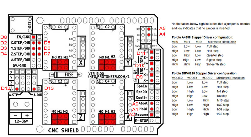
I’m still working on the electronics. I have all the Digital and Analog pins mapped to what they are on the CNC shield as they are labeled differently. I used this link for a lot of the information and a simple Arduino sketch to verify what I thought they were. Arduino Compatible CNC Shield Instructions
I created this image from that page and added the Digital and Analog pin assignments.
I am replacing the joystick with 4 momentary push buttons and a different color LED attached to each to see when they are pushed. Thought I would use a 470ohm resistor on each LED, so it is not as bright as 220ohm that seems to be mostly used for this. I can always change that if it is not bright enough. 1 button for Motor On/Off, RPM, Speed Profile and a Timer. I am also going to add a piezo buzzer for the timer to beep each minute for the timer. I have a 1602 LCD display hooked up with the backpack to make the wiring much easier. Since I seem to have plenty of pins, I will add 2 thermistors to the outside face of the flour sifter and a MAX6675 Module + K Type Thermocouple Sensor. For now, I am using jumpers on all these but will eventually solder them on.
As soon as I get the internal paddle system working, I am ready to try another roast test.
My neighbor and his wife did the wire baffle for me last night. He used the 20 mesh 304 SS and she pulled some strands of the edges of the mesh for the wire to sew the ends in place. I had to increase the vref on the DRV8825 from the .45v I had as it stalled when the beans snagged. I was shooting for .6 to .65 but got .75v so I tried it there. I ran it with beans in and no heat gun for 5 minutes and the 1.5a motor is only slightly warm and the DRV8825 is only a little warmer so seems like a good setting to start with. I was using the 3.63:1 gear set at 120rpm so the handle should be running about 33 rpm. I am going to have to try a roast today. I am still using the same electronics setup from last photo with just the joystick and the 1602 display.
After 3 good roasts, I declare this machine a success. I still have some tweaking to do but works better than I expected it to. Here is a video of the 3rd roast I did today.
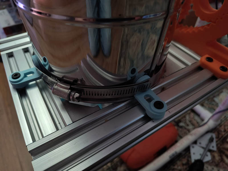
Think I found the solution to my last plastic getting too hot around the sifter. It was getting above 125c behind the cork near the end of the roast which seems to be a little too hot for that although the cork still looks ok. From the google searching I have done, seems like it should handle up to 120c. I don’t like the iffy situation and have been looking for an alternative solution to clamping it down and think metal L brackets behind a SS band clamp will work. I found these Amazon.com: Rierdge 24 Pcs Slotted L Brackets Heavy Duty, 18x18x30mm Adjustable L-Shape Corner Brace, Metal Right Angle Brackets for Wood, Furniture, Shelves (1.2 Inch Black) : Tools & Home Improvement and did a fusion 360 mockup in plastic of them but made them thicker so they would withstand the test. They are 8mm holes and they need to be 5mm for the V-Slot. I will initially try plastic M5 washers as I don’t think the heat will go that far out. I do have some M5 washers, but they are 10mm OD which barely covers the 8mm. I found some 15mm OD on Amazon and probably could find something the right size at local hardware store if i really needed them. Here is a photo of the mockup setup with 3 of those L brackets. I have to put a spacer below the L bracket to get above the bottom lip on the sifter.
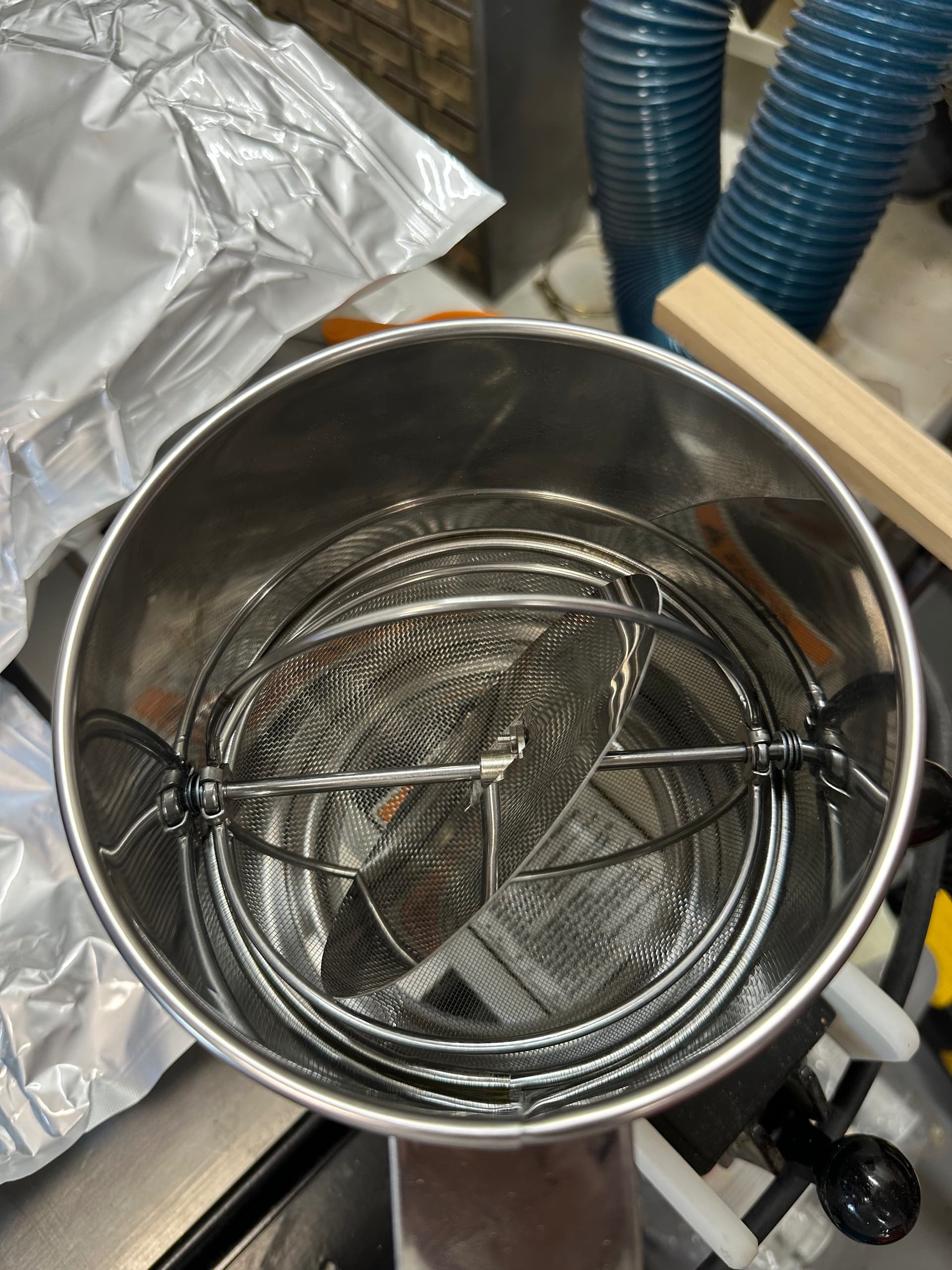
I made a wobble disk yesterday as per the Make articles linked way above. This thread has awakened this long dormant project of mine. Bought the parts ages ago.
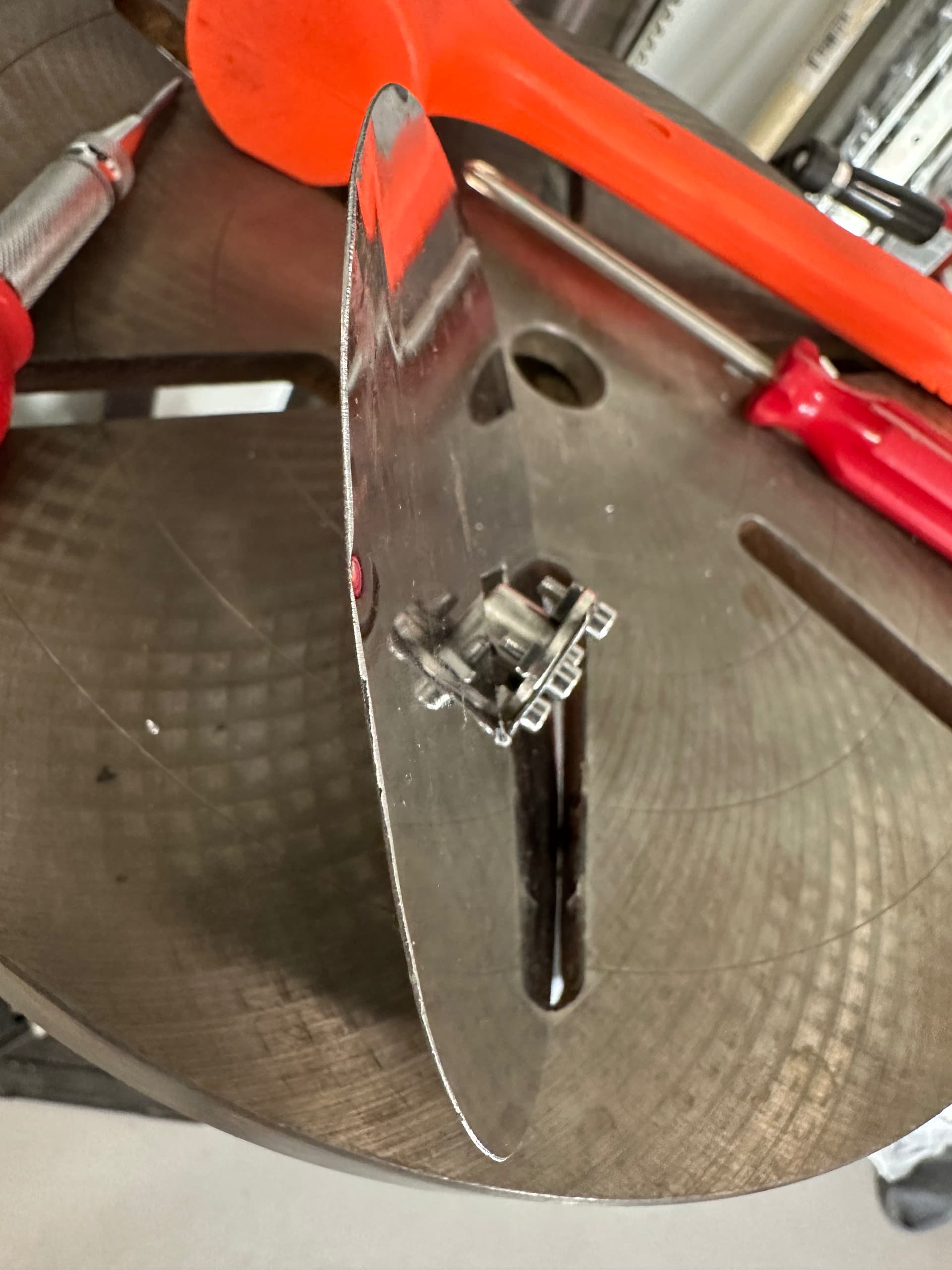
Thanks for posting that. Did you cut that middle shaft to get that flanged coupling in there or were you able to pull that shaft out. It is cool the way you still have the 4 outer wires still there. That does seem to be the way to go with this. The wobble disc would probably solve my problem with the beans getting caught on that middle lip as they probably would not go above that lip. Did you use an aluminum disc or SS? What gauge metal did you use? I see 304 SS 22- and 24-gauge sheet is available as well as SS couplings. The SS couplings do seem to be more expensive.
I might have to get another flour sifter to take apart like @jono035 suggested. I need to stay on track with my 1st version before I change paths though. I keep getting sidetracked from finishing my electronics.
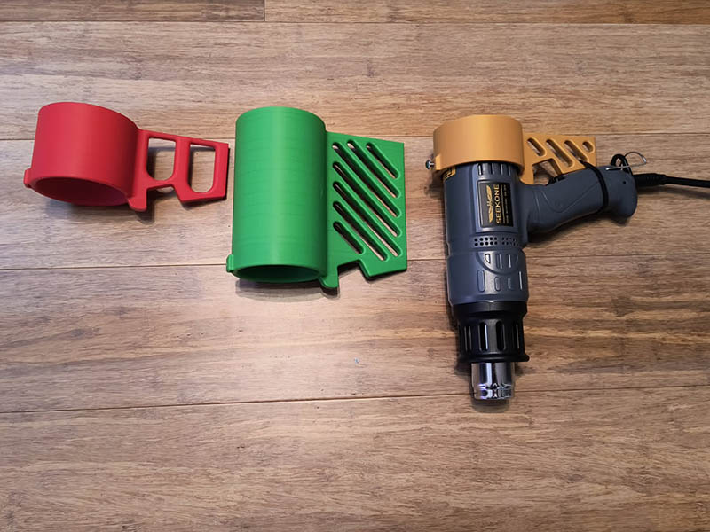
I did another roast yesterday using my same plastic clamping system since the L brackets have not arrived yet. Now that I am happy with the height of where the heat gun is, I shortened that bracket by 100mm and also cut 100mm off the height of the PVC pipe. That does make the heat gun less top heavy. I started out with the red mount when I tried the flared attachment on the heat gun. I would like to come up with some way to adjust the heat from the side easily without having to do it from the end.
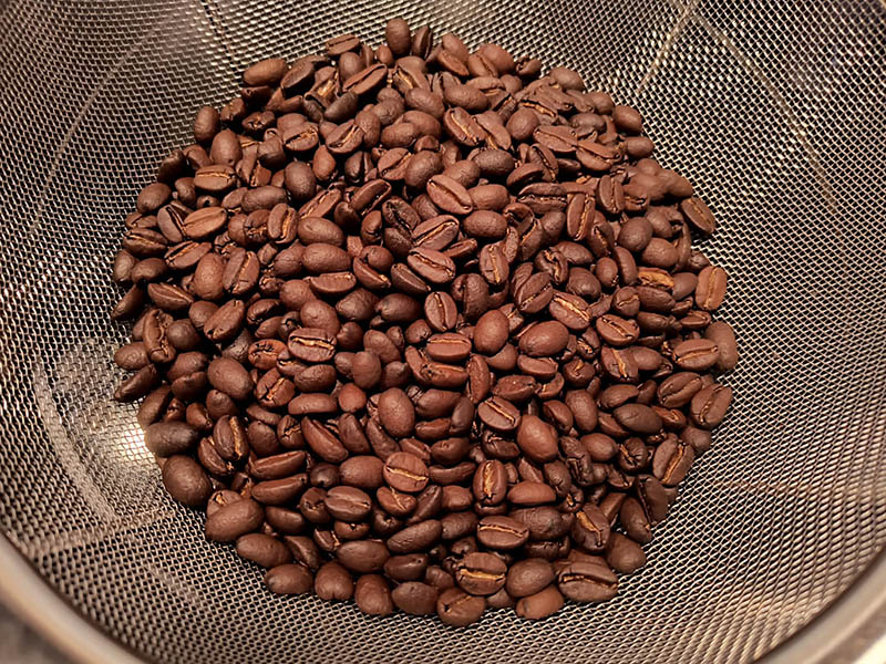
I was doing 4oz (113.5g) batches before. I used 6oz of green beans this time and only had less than 4oz when the motor was bogging down. I guess some beans got caught. Since I had not done 6oz yet, I did a dry run without heat. To give the motor some more torque, I switched from the 3.63:1 gears to the 6:1 and that solved that problem. I changed the motor RPM to 180 to keep about the same drum speed of around 30 rpm. I was thinking it would take a bit longer to roast, but the time frames were within about a minute of being the same. I did pull the roast before it really started cracking as I was concerned about the temperature the cork was getting. It got to 169c behind the cork at the bottom whereas it was around 125c with the 4oz. I was thinking it would take longer to roast with the extra volume. Maybe my temperature measuring was different from the other roasts. I will not have to be concerned with that heat when I switch to the L bracket and band clamp. Here is a photo of the roasted beans. They might have a little variation in color.
Think I have come up with a suitable name for my design. See how this sounds.
Planetary Bean Bouncer V1
My wife came up with the bean bouncer part. I was looking for something that described the unique part of this design. After asking “It who should not be named” for some name suggestions, this one fell into place. It wanted to use Planetary Bean Bouncer 9000 among other things.
Not clear the flour sifter I bought on amazon years ago still exists, but the shaft unscrews (from both a nut on the opposite side and one side of the “egg beater” is threaded on that end) - so I just bought a 5mm flange and ran the shaft through it. I just bought a little sheet of hobby stainless at the hardware store, don’t remember the gauge, it’s held pretty tight by the egg beater.
It doesn’t look like you’re using the Spindle Enable pin, but be aware that the v3.00 shield was designed for an older version of the grbl/gnea firmware. The newer firmware will work, and most everything about moving the stepper motors is fine, but to allow for PWM control of the spindle, they swapped the Z endstop and Spindle Enable pin in the later firmware configuration. No one ever updated the silkscreening on these boards.
Feel free to hit me up with any questions when you get around to firing this up if you’re having problems.
Actually, I am not using grbl. I didn’t initially realize I could use this board without grbl or else I would not have tried all those different motor possibilities. This shield will run with just a standard Arduino sketch. I did run a test Arduino sketch to see what pins are available on the shield and you are right, no pin shows up for SpnEn. I tested each pin for being either A0-A5 or D2-D13. I just put a jumper wire from a GND pin to each pin in succussion and it displayed what pin it was if it was one of the pins in that array. A3 is the only pin that did not show up for me in that test, but I could solder a jumper wire on the UNO if I really needed another pin. D2, D5 & D8 are used for the X motor which is only motor I am using. A4 and A5 think I have to use for the LCD and the thermistors apparently have to use an Analog pin, so I am using A0 & A1 for those. I will probably switch to a thermocouple at some point instead of one of the thermistors. I might have 1 spare pin after the 4 buttons, 4 LEDs, LCD, buzzer and thermistors.
Glad you’re making progress and getting what you need.
It’s been a long time since I looked in to “what’s new” with grbl, and now it looks like they’ve juggled the pin assignments again to enable self-squaring, but that breaks the PWM control for spindle speed/laser intensity.