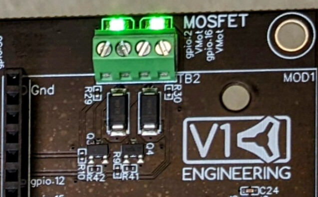
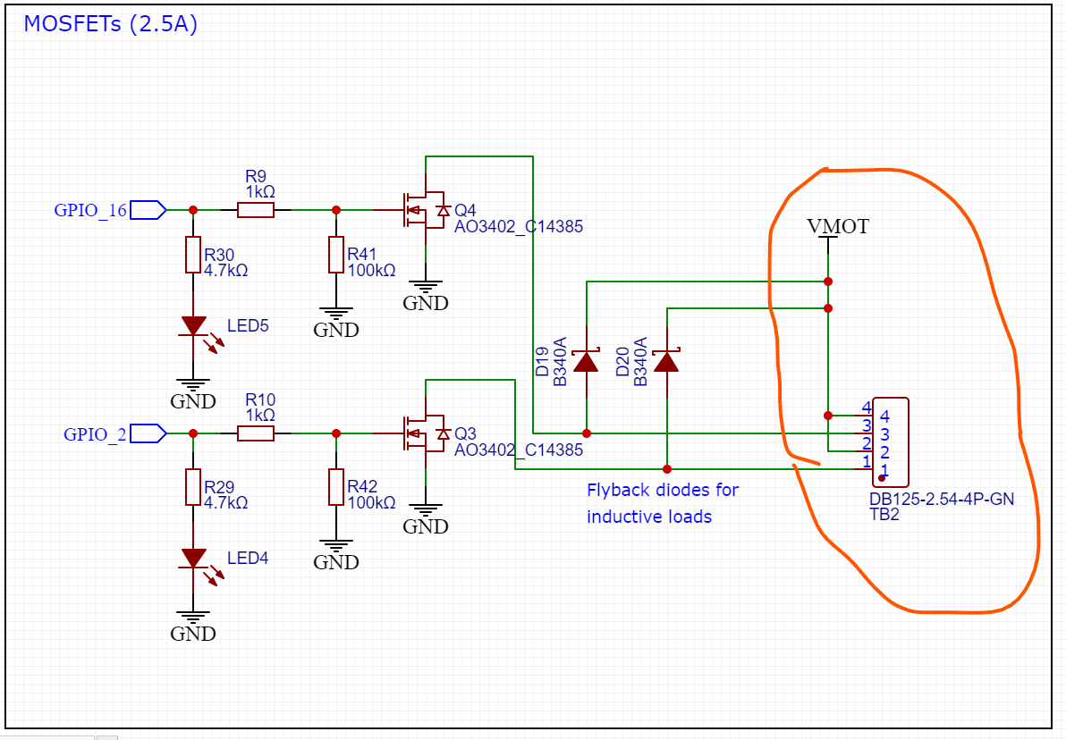
With FETs that small, it might be a struggle getting the FET to survive the I2T let-through energy of the fuse before the FET smokes itself.
I’d say that if it’s going to be a fuse, it either needs to be in a carrier or be self-resetting like a polyfuse. If it’s a soldered on SMT fuse then you might as well just replace the FET anway.
Polyfuses are typically super slow, have a huge I2T energy let-through and have some pretty intense temperature sensitivity. Fuses can be somewhat better but the ultra-fast ones that are appropriate for protecting smaller silicon tend to be super expensive.
From looking at some specs, it appears the maximum safe instantaneous current for that FET is ~15A, so there’s a good chance a serious short on a power supply with a decent amount of capacitance will exceed that anyway, making it unprotectable. The FET is at 1.5V forward at that point, so around 1.5 ohms of resistance, which is very high impedance for a deliberate or accidental short. The safe operating area is around 1ms for a 15A resistance limited pulse so assuming we added 1.5 ohms of resistance in the PTC/fuse/etc then a dead 24V short would be survivable for 1ms.
By comparison, a Bel 1A hold SMD polyfuse will take around 40ms to trip at 20°C. At -20°C it trips at 60% higher current which means more than 60% longer trip time while at 60°C it trips at 60% trip current, so will likely nuisance trip even at 1A. They’re also $0.50 in the quantities that would be used here so would add $1 to the board for the 2 channels. The minimum trip time for the polyfuse is around 30ms so if I were determined to protect that FET from a dead short with a polyfuse, I’d need to limit the prospective short circuit current to probably around 6A or so. The lowest rated polyfuse from that series will trip at 30ms at 10A which is too much, so to match that up, I’d need to limit the PSCC more to maybe 3-4A and use a 300mA polyfuse. So that would take the ~4A, 50mR open drain output and turn it into a 300mA 6R open drain output. That’s without worrying about operating at anything other than 20°C which will push further away from those specs.
A Littelfuse 1A rated very-fast carrier fuse will trip in 3ms at 15A which is still too long. A 500mA one will blow in 1ms at 10A which is probably the closest I’d be willing to go. The specs are also WAY more stable across temp, with it being +/- 5% in trip current from -20°C to 80°C. That would actually be likely to protect the FET but would result in a 500mA rated output with 1.5R of resistance. These parts cost more like $2 each for fuse and carrier so ~$4 per board.
So trying to protect those FETs from a short is going to cost a lot of ruin their performance. A better option would be to move to bigger FETs with more capability and more thermal mass so their safe operating area is larger.
I typically prefer to use open-drain outputs for stuff like this because they need less protecting. A wiring short to ground can’t hurt them, it just results in the output being always on and is far more likely than a short to Vcc, outside them being miswired or trying to power a dead component, both of which can happen with high side switches as well. They’re also dramatically cheaper to implement and typically higher performance to boot.
My approach would be to put a warning in, point out that it’s possible to replace the FET if it dies and you’re ok with SMT soldering and call it a day. Even with the protection measures above, I suspect it would be a net negative for all involved. They’re expensive enough that unless 10% of boards were dying in this fashion, it wouldn’t be worth it.
If it proves to be an issue, moving to a bigger FET that’s easier to replace would probably be my first port of call for a board this cheap/simple.