Wired LCD. Easy no networking.
I have a dev board available. If you want that, 10mm bigger, one slightly different vmot mosfet.
Wired LCD. Easy no networking.
I have a dev board available. If you want that, 10mm bigger, one slightly different vmot mosfet.
Size dont matter. My printer takes all the hard work
It’s not all that obvious but if you set idle_ms to some other value than 255 then the steppers will switch off after a short while. 255 means steppers will stay enabled after boot.
stepping:
engine: I2S_STATIC
idle_ms: 254
in protocol.cpp:
if (config->_stepping->_idleMsecs == 255) {
// Leave steppers enabled if configured for “stay enabled”
config->_axes->set_disable(false);
return;
}
Doesn’t that also mean they will disable if not moving?
Curse those thin buttons on the side! Class action lawsuit!!! ![]() LOL
LOL
Yes, and this will be a problem if for example you need to manually stop the router or spindle and the motors switch off due to idle timeout while the spindle is still on. I am looking into a way of disabling the motors initially during startup but leave the stay enabled feature on.
Question: do you think you will need to make available custom versions of the fluidnc firmware with v1 logos and custom macros, etc?
I’m using a step up/step down transformer that can either convert 120v into 240v, or do the reverse. I have only one dedicated 220v plug in our garage for an electric dryer. But it’s not near where I have my plasma rig. I actually now have two bits of machinery that require the 220/240 V and I drive both of them with that step up/step down transformer. I bought it from AliExpress. It works great.
The custom stuff is pretty easily just uploaded. I do not think I actually need to do anything super custom, just make a file with some common commands.
I use a pause at the end of my gcode. I can test it but I assume that will keep them on like usual. So boot with idle=0 and use pauses at the end of the gcode. if it stays powered on while paused, I think that is exactly what I want…oh, except If you home and move to a new starting position we need them to stay enabled. Let me play with it and see what happens.
I am fine with it booting powered up really, I just wanted to see if that would fix the USBC boards. Hooked them to the scope they use the pin0 slightly differntly so they will nto wok for this.
Darn sticker. I swore that was a lcd display!! ![]()
So what is the reports? When it reports status to webpage?
How often it updates the web page or maybe just the terminal. Not exactly sure.
Okay 10 more boards are in route. I think I have enough esp32’s for them. More of both on the way.
Drivers…I am short but more are on the way. So I can borrow some from the skr inventory.
5 more behind that. Then a large order. Slow Rollout.
This part of the UI:
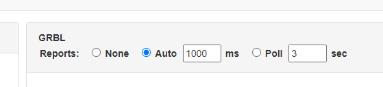
controls how often it updates when running a job. I assume the web page is polling at the specified period and it floods the controller with requests if the number is too low (too frequent).
I thinks it’s a websocket with the “board” getting told to send reports every x milliseconds, as opposed to polling, where the web interface will poll/call the “board” every x seconds (which is indeed a lot more ressource consuming)
I think you’re right, especially given there is a “poll” option next to it, which I apparently didn’t see.
I have some more observations, but separating into a new topic so this can be perhaps more focused on the Jackpot board.
Just thinking out loud here:
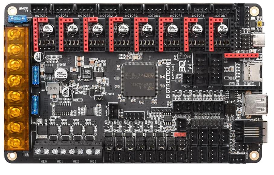
The ports on the Jackpot board are labeled X, Y, Z, A, B, C.
For MPCNC, X1=X, Y1=Y, X2=A, and Y2=B, and C is available for something else.
For LR3 (I assume), X1=X, Y1=Y, Z1=Z, Y2=A, and Z2=B, and C is available.
What if the ports were labeled X1, Y1, Z1, X2, Y2, Z2? Then for MPCNC Z2 is empty/unused, and for LR3, X2 is empty/unused? Would that be simpler to explain in the instructions compared to mapping A and B to X2, Y2, and Z2 depending on context?
The endstops could be mapped the same way X1min, Y1min, Z1max, X2min, Y2min, Z2max, and probe for the 7th. Maybe not on the silkscreen since there is no room, but for those pinout diagrams there wouldn’t be ambiguity in the mapping.
I second this about the naming/mapping
It makes a lot of sense to me. We actually discussed this when doing the labeling initially. We went with the “standard” labeling. Just in case this turns into a wider used board.
I am not opposed to this at all.
It means the drivers would get shuffled a bit, but that is nothing difficult, config file not difficult.
It does mean the first 30 or so boards will be labeled the other way.
Is there any more input on this? Will it make it more clear or less clear?
Don’t have a strong opinion, but…
Optimizing for least confusing assembly instructions, for immediately targeted machines makes sense.
However, am hoping to see the board used for variety of machines in the future. No idea what you’re planning though.
Personally, I like numbers 1 to 6, with simple table in the docs explaining what goes where. Like Octopus…
Expecting assembly doc will have a marked up pic of the board anyway.