They were both on the through hole headers, so I am not sure if those are automated or not.
1 Like
For a small run like that with so few through-hole components then I would expect it to be hand soldered. Regardless, that should be an easy catch in final QC. This is where having a test plan that can catch some of this would work when doing larger orders. Honestly, it’s not a good sign, though, and I’d contact them and call it out.
A simple option that I’ve used before is something like another board that can go on top of the drivers with LEDs on each of the input lines for the drivers, then some custom firmware that cycles through them one at a time. That way the QC criteria is that every LED should light and no 2 LEDs should be on at the same time, something like that.
One was an input so the LED was triggered, the other was on a driver and it stopped the board from powering up. Not sure if there is an easy test for that. I even looked at the endstop one and missed it. Tiny little wisp connecting them.
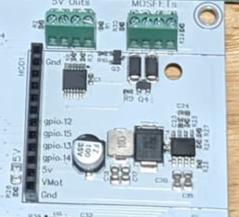
Now that I look at it more. Hand soldered for sure. The white mask is burned on one side of the pins on all the headers. Hot iron darkened the pretty white mask.
Getting exciting. Learning a lot about FluidNC quickly. So far I have found all the info I needed pretty easily. That is a good sign.
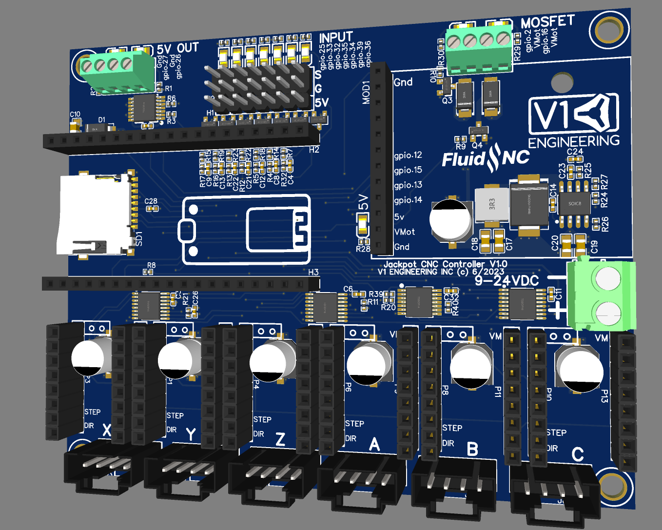
Picture so you can easily see a size comparison. I can make it a bit smaller, not that it matters much at this size. Don’t pay much attention to the graphics that is not the final form.
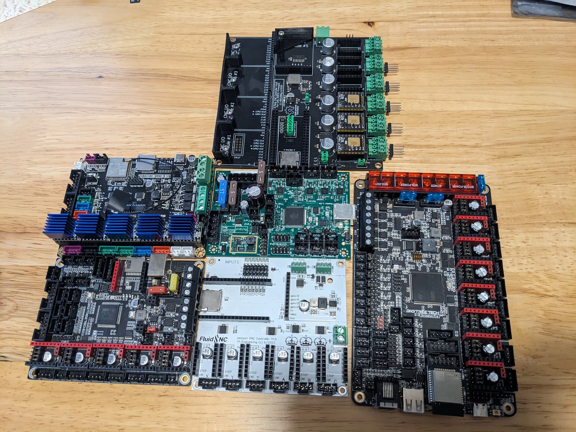
Kinda crazy how small the components are. I have been staring at them on a big screen zoomed in, freaking tiny! Bart is a genius at this stuff. What he pulled off in a short time, I have been spending days just doing tiny tweaks.
The esp32 runs pretty hot, or hotter than I remember.
6 Likes
Just having them power the board up will find stuff like that. Set a required input current range for the board while it’s doing its self-test routine (or just doing nothing) and that’ll show a lot of stuff up.
Even just power LEDs on each rail can help with that.
Looks good!
2 Likes
I hope the production versions are red ![]()
Just a wild thought but since we don’t need to access it once it’s up and running, no sdcards or usb ports or whatever; it’d be cool if the form factor lent itself to being mounted inside the X rail, maybe with a panel mount connector on the back strut plate for plugging the core cables in.
2 Likes
Ryan, yes they run kind of hot (and pretty sure you have a lot better ambient temperature to begin with… Mine is over 36) but Bart’s 6 pack uses a shroud with 2x 40mm fans
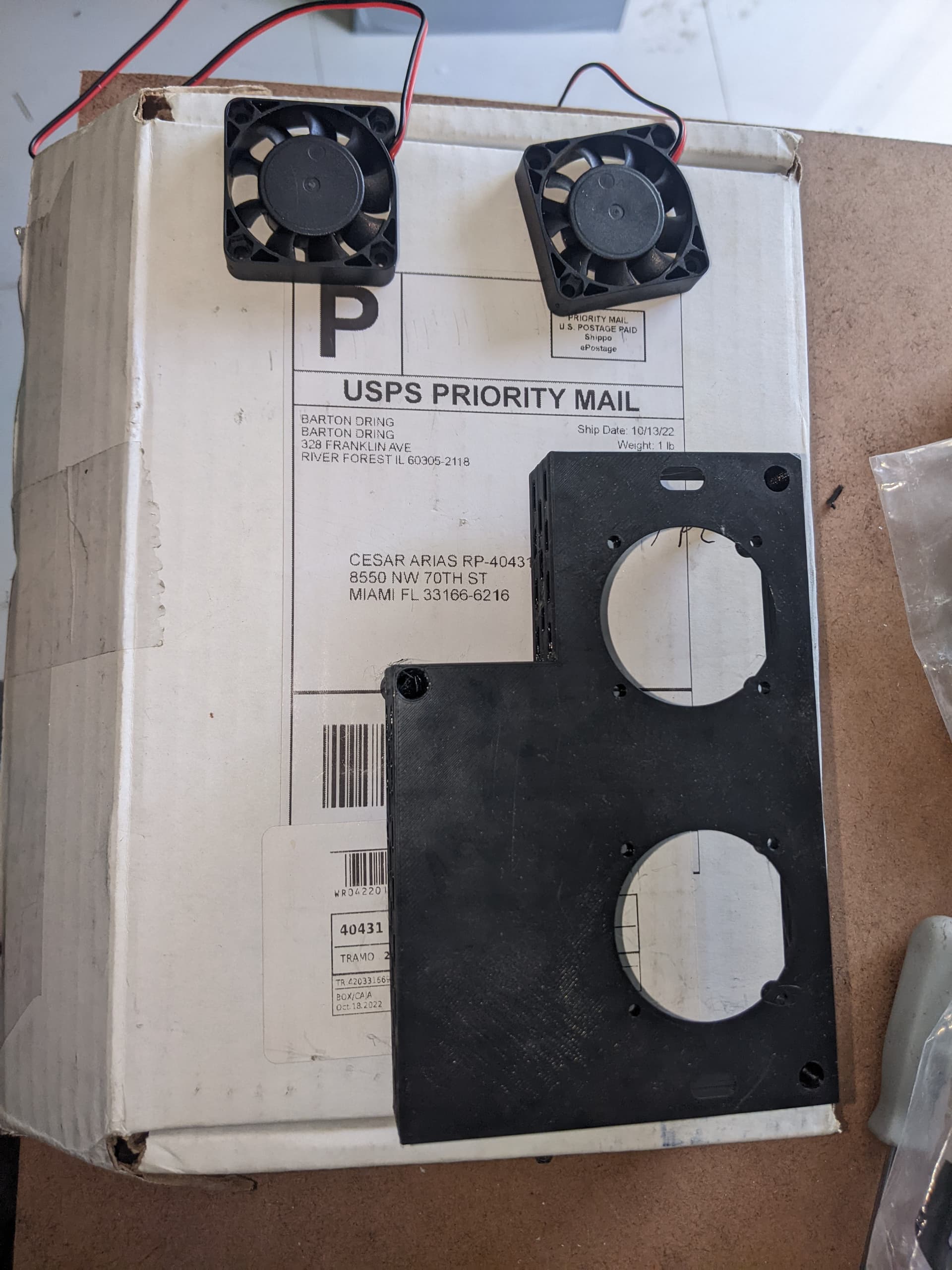
4 Likes
heh, I still don’t have fans on mine.
1 Like
That is the Dev board. It is set up to run drivers as large as the 5160…those need cooling at full tilt for sure.
I am confident we can get away with no fans, but the case will need to be a bit more open than the two tiny holes we have now.
1 Like
Playing with the colors, for sure. Maybe even switch each batch for a while
1 Like
If yours is running fine then you are set. I used to run mine without fans for a while but then temps started to raise as i often see 40+ambient inside the shop i did placed the 2 fans. My issues were with printed parts (motor are working at higher temps for me ![]() ) and deforming no matter what current settings are used -while keeping enough strength to do dome cutting-
) and deforming no matter what current settings are used -while keeping enough strength to do dome cutting-
Also, check about the esp32 working temp range, then can withstand serious amount of heat. +100°c
1 Like
I guess with one fan to circulate some fresh air tha board will be all set. We all can design something to place a 40mm/80mm fan in it.
1 Like
Booo! Needs RPGs!
3 Likes
I’ve got a120mm. ![]()
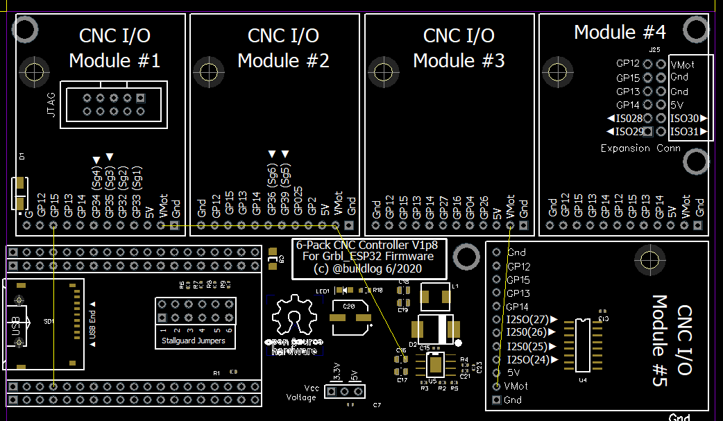
The expansion port looks similar to the expansion ports on the 6-pack controller but only gpio 12, 15, 13, 14 are marked:
I am guessing this is more or less equivalent to expansion port #4 on the 6-pack controller, where 12, 15, 13, and 14 are replicated twice? Or do those upper pins have no connection?
I’m not aware of a pendant for the 6-pack board that fits into one of the expansion ports, unless someone else knows of one? Would be cool if someone were to develop a pendant/joystick and it were also compatible with the 6-pack. Not too many I/O available though, so probably an external microcontroller that handles the joystick, and that way a bunch of other functions can be added like a dozen buttons or maybe a little oled.
1 Like
" Pins 5-8 On the 6 Pack, pins 5 through 8 are being reserved for data buses, like SPI, I2C, I2S, etc. Only the first 4 pins are being used on the current modules. All of the module sockets are connected to the same 4 I/O pins on 5 through 8. Socket #4 also has those same pins doubled up on 1 through 4. This allows you to use a normal module on the pins reserved for data bus pins. If you have a special need to use more than 4 pins on a module, you can, but be aware of the impact on other modules and socket #4."
Yeah that allows full functionality. He specifically mentioned a Pendant. The whole new idea on this board was to allow for 6 UART drivers while keeping a spare UART pin for other things on the module port.
I saw that module definition and I was a little confused as to whether there was a “standard” that was implicitly defined.
For a random I/O module in a random slot on the 6-pack board, it seems like the firmware would have to be configured to route the function to the right pins. I’ll assume FluidNC makes it easy and has the options pre-defined, so you just tell it which module is in which slot, and it maps the functions to the appropriate pins.
In this case, for the Jackpot board to take advantage of the existing modules, it looks like the pin definitions for slot #4 of the 6-pack board can be used. If the existing modules use only 4 pins and if FluidNC has definitions that allow a module to be used in slot #4 of the 6-pack board, then those same definitions would allow that module to be used in the expansion port of the Jackpot board.
I’m thinking the pendant I/O module would need a serial connection and not bit-bang generic GPIO, so it would need GPIO 14, 13, 15, 12. ![]()
I was originally thinking perhaps with jumpers the pendant module could fit in another slot (besides slot #4) of the 6-pack controller and use pins 5-8, but I’ve talked myself out of it. If the pendant were to use jumpers and plug into e.g. slot #1 of the 6-pack controller and use pins 5-8, then slot #4 would be unusable anyway. So there is no point to allowing the pendant module to take advantage of pins 5-8 and it might as well require being in slot #4.
That constraint simplifies things. The pendant only works in slot #4 of the 6-pack controller, and the Jackpot board effectively has only slot #4 from the perspective of FluidNC. If not using the pendant, then any other module can go in the Jackpot board and configured as if it were plugged into slot #4 of the 6-pack board. Again, this is assuming FluidNC has the mapping covered.
Sorry if that’s confusing. Just trying to think ahead about the different possibilities.
No, I don’t think so. You can grab the sample definition and drop it in your config yaml, from there you tell it which pins to use. For that reason I am labeling all pins on the top and bottom.
Honestly I am not really sure. The 6 pack from what I can tell has the important pins 12-15 mapped to all module ports just in case you do not want your important card in slot 4, then you would need a custom card to fit. So basically #4 is special and that is the one we kept. The other pins are just regular IO.
1 Like