Configuring Marlin for SKR 3 EZ

Hi Andy and Jeff,

endstoppullups were already enabled, so not this I think

pronterface does report each axis second endstop, note no endstops are connected to the board here

with an endstop present on x_min or y_min, this triggers the endstop and its second counterpart (i.e. x2_min and y2_min respectively). When measured with a DMM they are measuring separately

I enabled ENDSTOPS_ALWAYS_ON_DEFAULT but that made no change

is it me or do we have the logic backwards here, with an NC switch attached I see 0V and for a pullup that is what you would expect to see with a closed switch. When I press the switch (i.e open the switch) I get 3.3V. So the pullup is working as expected, so for triggered logic they should trigger on a high signal and not a low one.

you can see here the logic is set to low

im just wondering why pronterface is reporting x2_min and y2_min, we have defined these endstops in Marlin as X_MAX and Y_MAX

image
in configuration.h

in pins we set the dual enstops as X_MAX and Y_MAX

this lead me to looking through configuration and configuration_adv for X_MAX

in configuartion_adv I found this snippet of code regarding dual endstops

where I underlined was commented out, I uncommented this and flashed the board with the new bin file and hey presto we now have M119 reporting each endstop correctly :grin:

so to get endstops working correctly I had to set hit states as high to work with pullups and NC switches and uncommmented these lines and there we go, all is well with the world. I can now set this up with the MPCNC and start squaring. Thanks for all the help lads, hopefully this will help someone else down the line

You need to be careful when talking about the x_max pin, x_max logical endstop and the max x endstop axis.

The text “open” and “triggered” is out dated and based on NO endstops.

I’m a little confused as to what you’re trying to do here. We figured all this stuff out before we built MarlinBuilder releases. The changes we actually make to the firmware are listed here:

There are a lot more things we change for the rest of the system. Most of these lines are direct calls to other files with more config changes:

Hi Jeff,

I would imagine anything I say here would be confusing to someone who is familiar with configuring Marlin, I havent looked at Marlin firmware in 10 years since I was at college and I’ve only been looking at it this week. I am like a blindfolded man in a dark room feeling around to find the exit compared to someone wearing night vision.

There is no Marlin build for the SKR 3, I got the wrong board a year ago when I initially was planning on building a lowrider but ended up not doing so and have now just got round to building a MPCNC which suits my purposes for now. So I am trying to do so with the SKR 3 to avoid having a motherboard lying around the place doing nothing.

Andy has been so kind to edit the most recent bugfix version 2.1.x of Marlin (required for the SKR 3) to work with the MPCNC machine which he provided to me and I have found issues with how it handles endstops and everything I have documented here was me working to fix that. All be it in a fumbling kind of way.

How and ever following your link to the git to the auto builder and following along with what it does I can see how it works and should be able to implement these changes in the config manually for the SKR 3!

Hope this make sense and explains the reason behind the faff

1 Like

well its 5am and I couldnt sleep until I had followed the Marlin builder @ src/configs/V1CNC_SkrPro_Dual_2209 :sweat_smile:

I have done everything other than set the laser settings, the laser will go on pins PB5 and PB6 which the pins file for the skr 3 sets them to, these are the fan outputs. We’ll leave this as todo until I have tested everything else.

I took a systematic approach, start from a fresh marlin 2.1.x bugfix folder and used this as a working copy.

First I set the config up to work with SKR 3 boards, i.e. chipset, board name and serial ports. After this I followed the following steps in the build, making a build each step and saving the config files for each step in its own folder in following order

  1. v1-base-config
  2. cnc-config
  3. TFT35_e3_v3_CNC (this after cnc-config to fix CUSTOM_MENU_MAIN requires an LCD controller that implements the menu error)
  4. skr-pro (only settings that didnt overwrite skr 3 settings)
  5. tmc2209
  6. dual-drivers-on-xy
  7. skr-pro-dual (works for skr 3)
  8. and last steps in V1CNC_Skr_Pro_Dual_2209 builder

This builds nicely, as I said I havent tested anything but it should work without issues and be the same as MPCNC for the SKR Pro board, Im hoping at least

Andy this should fix the issues you’re having with getting the screen working :slight_smile:

Working Copy V1 MPCNC on SKR 3 cfg Files.zip (105.3 KB)

1 Like

I see what you’re doing now and I looe your new approach. I’m glad the scripts left enough breadcrumbs to so it manually.

Another potential piece of help is to look at the resulting .zip from MarlinBuilder releases. They include a .git folder and you can do a git diff on them to see what we changed from that version of marlin. A lot of changes would be deleting the extra HAL folders. The remaining should be stuff that matters.

I like your current approach though. It may not be perfect, since we haven’t tested against the most recent bugfixes.

its more of a signposted path than it is breadcrumbs I’d say

  • set settings for the board you intend to use, chipset, motherboard, steppers
  • find a board thats comparable
  • go through each config in as close to the order as laid out there as possible
  • opt_set : setting a value, just search through config and config_adv file and maybe pins files and set the value, enable if not already
  • opt_enable : enable anything under this
  • opt_disable : disable anything under this
  • ignore anything like echo or file management, this is just coder faff that sanity checks the build

doing this you should be able to set it up to work with any board thats supported by marlin and have the same configuration and functionality as laid out by V1 :slight_smile:

absolutely love it, the builder is set out in a very nice easy to follow kind of way. We could make this a guide for an unofficial way to support unsupported board types

1 Like

It is. A bit. But I know from experience that people can be intimidated by code. Maybe they won’t be if they are already configuring and compiling marlin.

Im a software engineer for test systems, mind in LabView so this is not my native language but I find once you know one or two languages you can follow along to some extent

It would be less intimidating if there’s a clear and concise explanation of what’s in the code

The builder doesn’t contain anything crazy like classes or calls to different h files with “hidden” function calls and it only uses a few extra file handling commands so its a fairly simple enough bit of code to follow (which is why I was able to do it :sweat_smile:)

Just a thought anyways, I am putting together a YT channel, if I ever get around to learning how to edit video, maybe this could be a video I could do

I’ll keep you guys posted on testing and if anything goes majorly wrong

1 Like

I believe the future of V1 CNC is FluidNC/Grbl/Jackpot. But as time goes on, there will inevitably be people who will want Marlin (I like Marlin) and the boards we tested on so far will be replaced. Having a more future-proof way to configure new boards and having the instructions in video format would help a lot of people.

1 Like

Cool. I have used a ton of test systems in Aerospace applications that are LabView based.

I think the mainstream will be FluidNC/Jackpot, but on the fringe will be Klipper, or Marlin, perhaps other user-specific implementations. The nature of an enthusiast community.

Heck yes, this would help tremendously in that special use case.

1 Like

Don’t forget EstlCAM as a controller…

4 Likes

well we have good news and some half good and half not so good news

firstly though

Hi MakerJim, I’ve done some work in the aerospace industry also, I work across industries in general as a contractor but aerospace is where you get to do big crazy rigs, scary but fun

VOLUME DOWN!!!

here’s a wee vid of centrifugal compressor test rig I did 5 or 6 years ago, 2 big 3KW motors in series, one controlling speed, the other torque, a 2 to 1 gear box which then went to a CVT which ramped it up to anywhere in the realm of 30 to 60K rpm. Had to control pipe inlet and outlet valves and avoid choke conditions otherwise it would blow the compressor, possibly also blowing up the £1M CVT and we wouldnt want that now would we :sweat_smile:

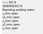
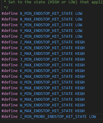
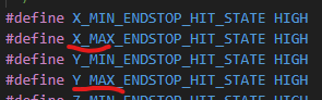
good news is the Marlin firmware seems to work in as far as I have tested it, axis motors all spin as they should and the correct endstops trigger as they should also. Need to get my belts all tightened up tonight and and get the gantry moving, then its a case of calibrating and then get it drawing on paper. Need to rig together the safety electronics also, E-Stop and contactors and such and then design and print a box to go under the table and then Thunderbirds are go!

Now for the half good and half not so good news, the screen updated correctly and shows the V1 logo and all the menus seems spot on however I get the dreaded no printer attached message but only with the touch screen mode.

The half good news is that Marlin mode works nicely :slight_smile: I can move motors from there which is very encouraging, the only thing that tweaked my awareness is that steps/mm were set to 200, 200, 800 but I reset defaults and it went to 100, 100, 400 so thats me happy there.

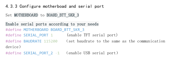
I checked the baudrate and set it to 115200 which is what the skr 3 TFT serial port is supposed to be set to

image

Wiring seems to be good because with just the TFT wires plugged in the screen only boots up with them in one orientation (wished they gave you the same connector on the board end of the cable instead of female headers)

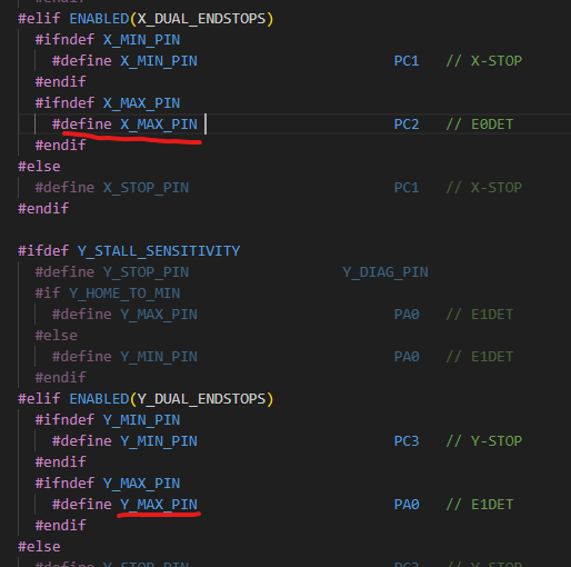
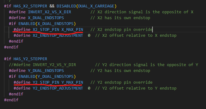
I could live without the touchscreen but its a nice to have, any thoughts or ideas on where to start looking? Surely theres not anything board specific about the TFT config is there?

Do you have the V1 firmware and config.ini on the screen? The stock screen thinks it is talking to a printer.

Good Morning Jeffedb3

I followed the instructions for the TFT screen here

https://docs.v1e.com/electronics/skrpro/#skr-bin

and got the latest version of TFT config from here

I just unzipped and copied and pasted the whole folder from there onto the SD and ran the update on the screen.

do you need the Firmware.bin file from the Marlin build on the SD also?

I know the instructions say “Flashing the screen takes a .bin file, the config file” but they then go on to say “Unzip the folder and load all the files on to the SD card like shown below” and picture shows no sign of a Firmware.bin, hence I just used the contents on the TFT package

Did the zip have a firmware.bin? Did it change one to firmware.cur?

I can’t remember how exactly it works. It has been a long time since I flashed a screen.

I think one of those should be renamed to firmware.bin. The instructions might be based on a time before we had two versions of the screen.

Or, maybe the screen knows which one is the right ine because of the name. That sounds familiar too.

Well I put the firmware.bin file in from my build

After flashing the screen this stays as firmware.bin

The config.ini is changed to config.ini.CUR and the TFT35 folder is changed to TFT35.cur, so its not using the firmware file and everything needed is in the touchscreen release folder

I’ve just read through the config.ini there and the only thing board related is baudrate and I’ve double checked all the required settings that need to be enabled and all are good

So kinda stumped on this one

Thanks Evan - will have a look over Easter at this and the other adjustments to see if this resolves my other issues.