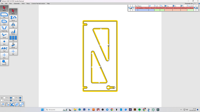
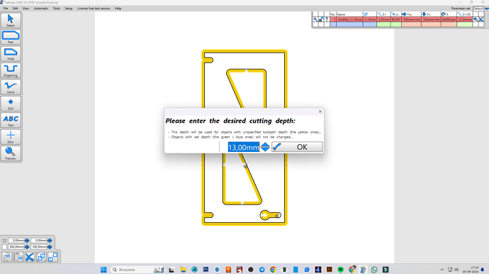
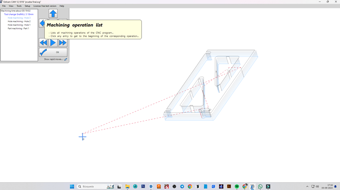
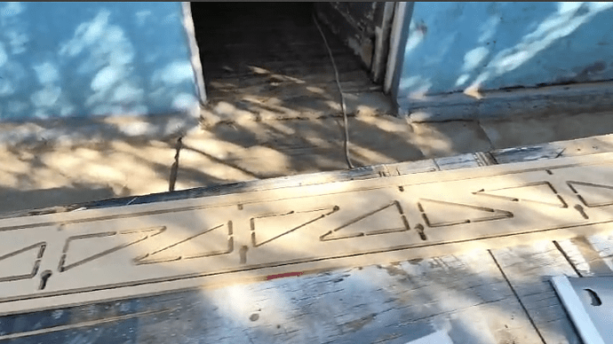
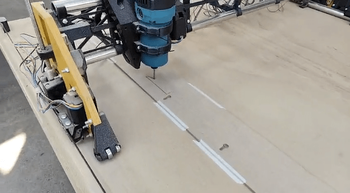
OK, I understood what you said and I have corrected it. Now I want to test before making the complete piece. I have made only one part but I don’t know why it goes down all at once when I start. I’m doing the test on a 12MM MDF and I’m recording a video of what I’m doing on stlcam to see if you can tell me what I’m doing wrong to make this happen.
I’m not sure I understand what you mean here.
According to the screen capture of the EstlCAM preview cut, it looks like you are taking several (6 or 7) passes for each cut. This equates to a Depth of Cut per pass (DOC/pass) of around 2mm (this is set in your Tool settings window). You could probably increase that to 4.5mm DOC/pass, and do the piece in 3 passes for your total DOC of 13mm.
Note that it looks like your Tab settings are a bit off, as the tab is almost 10mm high, whereas you probably only need about 2mm on a 12mm piece of MDF.
When you say that it goes down all the way, have you probed to the top of the work material using the G38.2 Z0 command and the Touch Probe? After you do that, you need to set the Z height using the G92 Zx (where x = the thickness of the touch probe = 0.5 for the V1 touch probe). That tells the controller that the top of the work surface is Z=0, so it will cut only 13mm total below that point.
Otherwise it is using the homing reference of Z=200 at the top of the Z travel, and the top of the travel is only about 70mm above the spoil board, and when you start the gcode file, it will try to move 200mm down to reach Z=0, with unwanted results.
Hope that makes sense to you…
Also, your Zero X/Y should be closer to the workpiece. ![]()
Thanks for helping me to solve the problem, indeed it was that when I sent to the Z gcode is at 200mm and tried to go down to 0mm so it went to the bottom stop. But using the data you provided me and also searching a little in the documentation I was able to solve the problem. I have another query, does anyone have their lowrider3 with a Makita M3700b. If so could you recommend adapters to use smaller cutters, I would appreciate it very much.
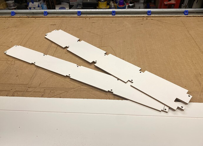
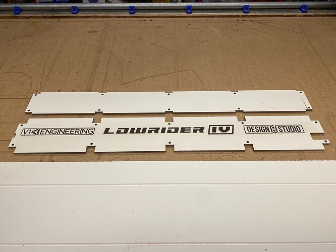
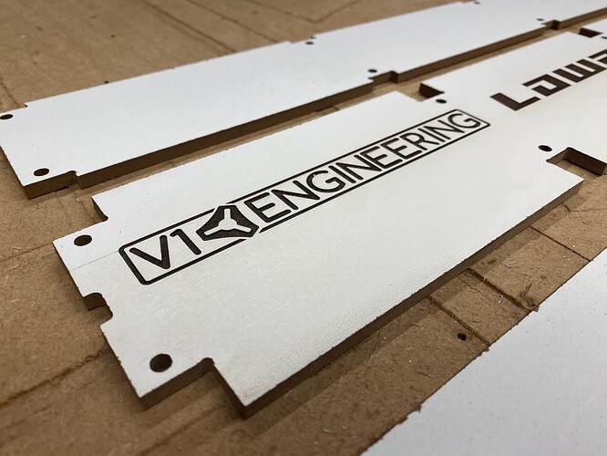
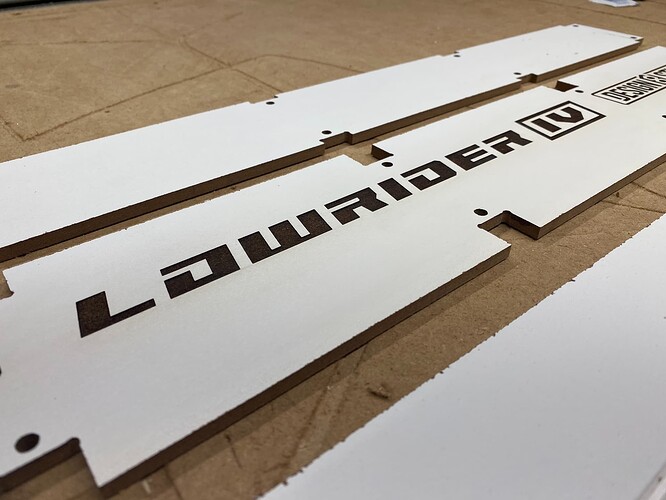
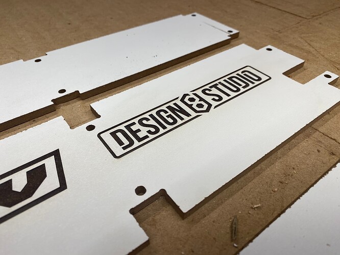
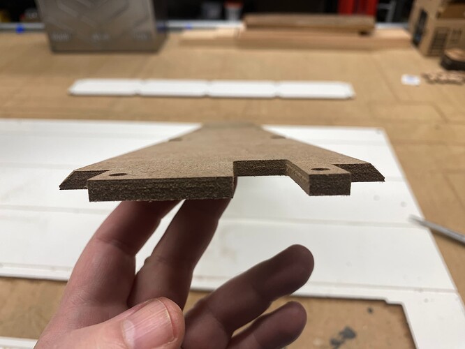
Our local home improvement stores sell hardboard only at 1/8" thick, and I wanted 1/4" if I could get it. I found out that Home Depot sells it as a product labelled as “wainscoting” — made to attach to lower half of room walls, and has grooves in it, giving the appearance of slats, and the grooved side is painted (primed?) white. The space between the grooves was more than enough for cutting struts. I found some of this in their scratch-and-dent corner, where they sell at a discount. For partially damaged sheet goods it’s 70% off. So I got all they had and it’s been great as the strut for my LowRider v4 pre-release testing. Plus, because one side is painted, it means when I did laser engraving on it, I got great contrast. Here are some pics of the struts I made from it:
This last pic shows thickness, but also shows that I used a chamfer (bevel) cut bit in my router table to bevel the sides of the protruding nubs that make these into “Jamie Strut Plates” aka JPlates. The beveling is a trick I came up with to get even more shielding from dust / chips, and even better aesthetic.
Thank you all for your help, I found cheaper cut MDF in a local store and I already have the brackets. I have some doubts if you can help me to dispel them. How can I make the sections where I am not milling to advance faster. How deep can I go, does it depend on the diameter of the tool? I hope you can enlighten me. Pictures of what was done.
If you are asking, how to make the machine’s rapids (jogs between cuts) faster, that is an edit to firmware, and “how” depends on: what you are using for your control board / type of firmware?
This also depends on various factors: look in the docs for “milling” getting started info. Getting the right “feeds and speeds” calls for coordinating the RPMs of your router, the diameter of your bit, the stickout (length) of your bit’s cutting area, how many flutes your bit has, your depth of cut, etc. We’d need more details to give specifics. However, one of the best things you can do for your own longterm success is choose a good source for calculating your feeds and speeds! There are free tools available. I did choose to pay a one-time fee for the resource I use, called GWizard Calculator.
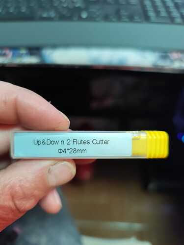
I am using V1 lowrider3 kit V1, SKR Pro1.2 board, 5x 2209 drivers, TFT35 E3 V3 the firmware 513 purchased by my aliexpress. My milling machine is a makita M3700G only has one speed and I am using this flute.
This means you are using Marlin firmware. That defines how to edit the firmware. It’s been a while since I switched over to using a Jackpot control board (bought from Ryan’s V1E.com store), which means I am now using the FluidNC firmware, which is easier to edit. On Marlin, I think there are some things you can edit in the on-screen terminal and save using M500 command, while there are other aspects that you have to edit the firmware, recompile the firmware, and re-flash the firmware. The knowledge that you are on Marlin may help you in your search. Also it gives a needed detail to various experts here on the forum who can help. I’d have to dig to find it. It’s easier on FluidNC (on Jackpot) because all you do is edit a text file that is named config.yaml, and upload the new config file and reboot.
The “speeds” part of “feeds and speeds” is connected to both the RPM of the router and the forward motion (feed rate) of the machine and the downward motion (plunge rate) of the machine. By your router only having one speed, it greatly limits your control over one of those three aspects. A Makita (or other brand) with a variable speed control dial would be much better for you. The crucial detail here and now, is how fast is the one speed you have, in RPM?
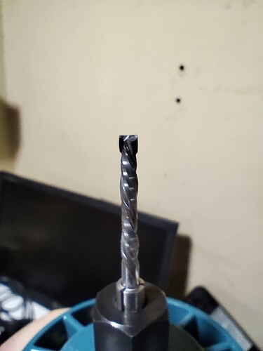
Can you show a photo of the bit itself, not just the package?
What is the diameter? 4mm? Is 28mm the length of the cutting blade part of the bit? I see it has 2 flutes, but is it a compression bit, as opposed to up-cut bit?
One thing to be aware of with regard to the router only having one speed, is that if that speed is high, you probably want to stay with smaller bits that have small diameter. The smaller the bit diameter the faster it needs to rotate. I’m thinking 1/8" bit (3.18mm). If the router’s one speed is low, you probably want to tend toward larger bits. I’m thinking 1/4" (6.35mm).
This is the flute. How do you power the lowrider and the router, I mean the power connection, do you put it on the side of the cabinet?
From what I could find, a Makita M3700G has a fixed speed of 35,000 RPM. That is going to be a challenge.
Is it a challenge because the speed is fixed and it is not fast enough?
It’s a challenge because it’s too fast for many of our cut operations.
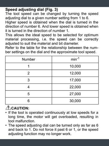
Most of us have variable speed routers in which the low setting is about 10,000 RPM, and the highest setting is about 30,000 RPM. Most of our jobs are cuting using speeds ranging from 10,000 RPM to about 24,000 RPM — This chart shows the speed settings on the variable speed dial of a Makita 700 series router (it’s also about the same range for the Kobalt corded trim router that is no longer being manufactured, yet some are still being sold in either primary or secondary markets):
On that chart, most of our users never use settings #5 or #6.
Some users never use higher than #1 or #2.
To understand the needed balance of feed rate speed of the machine and RPM speed of the router, consider these two ridiculous extremes.
Ridiculous extreme #1
If your bit is spinning fast, and the bit is down in the material, but your machine is not moving, your bit won’t be cutting, but it will be creating friction. Your bit will get very hot, and thus also soft. Soft means your bit gets dull quickly. Your material will also be getting very hot. In this scenario, your material will burst into flames in a very short time. This is one of many reasons to never leave a CNC machine unattended. If your machine’s forward motion ever stops during a cut job while your bit is in the material, turn off your router immediately.
Ridiculous extreme #2
If your bit is not spinning at all, and the bit is down in the material, and your machine is trying to move, your bit won’t be cutting, and it will not be creating friction heat, but your machine will bind up horribly and starting skipping steps.
So…
There is a range in between these two extremes where cutting works. But if you are moving the machine too slow in your feed rate, and your bit is moving too fast, you won’t catch your material on fire, but you will heat up your bit, and it will get soft, and it will get dull quickly, and it will take on an appearance of being “burnt” looking.
The act of cutting creates some heat. When the feeds and speeds are right, the cutting blades of the bit get to bite into the material and remove nice size chunks — chips — and much of the heat is carried away from the cutting operation in those chips as they get evacuated from the cut area.
But if your bit is spinning too fast and the machine is not moving fast enough, the blades are not getting pushed into the material very far, and they cannot take big enough bites, and the heat gets built up in the bit, and the tiny chips being created are not big enough to absorb enough of the heat. This gets you a burnt, dull bit, and poor quality cuts.
Your bit looks OK. In your current setup, with a scenario of a one-speed router and the speed is too fast, two flutes is better than one flute, because two flutes can work at faster RPM than one flute. Also, small bits (think 1/8" or 3.18 mm) are better than large (think 1/4" or 6.35mm).
The photo is of the cutting bit, in this case an end mill bit. A flute is an “opening” running semi-vertically along the bit in which cut chips can get evacuated from the material. Your bit seems to have two flutes.
Ryan recently suggested (in assembly instructions for upcoming LowRider v4) to run an extension cord into the gantry (the beam) and thus you can provide power to both the LowRider control board and the router, with only one cord coming out of the beam. This would have your AC-to-DC power supply stored inside the beam. This sounds like a neat solution.
Howdy, I’ve been stuck with my lowrider3 but I’ve got it ready to use (I’m still trying to figure out how to implement what you said Doug to power both the lowrider and the palm router). I have a question, if you could give me some guidance. It is with the tool change, how do you do it so that it does not move from the place where it is when I change the tool and do the work where it corresponds and moved?
For the Jackpot board, the easiest way to be sure is to just home the machine again after the tool change. It remembers the offsets (X, Y, Z) after homing. The Jackpot even remembers after rebooting.
For SKR, best to make a note of your X and Y offsets when you start the first operation, so you can then home and return to those same offsets after a tool change.
Either way, remember to again probe for Z height after the tool change.
Not true for SKR (which I think @vhlh310177 is using), I’m pretty sure!
For that application, the best practice is to home the machine before starting, then jog to the machine starting position. Make note of the coordinates, then use G92 X0 Y0 to set the X and Y position. Then probe the Z (G38.2 Z0), and before you set the Z position to 0 (or more accurately to the thickness of the probe), make note of the Z position.
Now if you need to reset everything to the starting position X0 Y0 Z(probe thickness), you just refer to your notes and move it to that position and re-probe Z/set Z height to probe thickness. Not as elegant as Jackpot, but easy enough once you get the hang of it.
The other option is to be very careful when changing the tool to not disturb the X and Y position. That way you only have to re-probe and set the Z position. Note that the motors will be sturdy in position for a few minutes, but if they idle for a longer time, the holding current is lost, and the motors can move very easily.
Sorry, it’s been quite a while since I switched over to the Jackpot, and I had forgotten that. Will edit my response.
