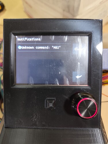
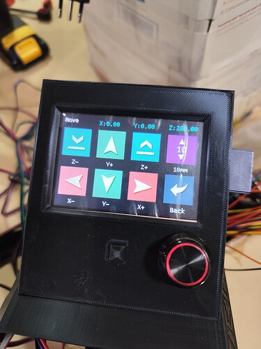
Hola, saludos a todos. Tengo el siguiente problema cuando energizo la placa y ya estando en el menú me arroja un error “M82”. Lo limpio presionando clear, pero no sé por qué me aparece ese mensaje. Y con el eje Z siempre me aparece en 200mm y no en cero como el eje X he Y. Y cuando quiero hacer Home en Z uno de los 2 motores sigue en movimiento y no corta el recorrido ( y es aleatorio). Me podrían ayudar con eso, de antemano muchas gracias. Pondré imágenes.
Hello
I’m using Firefox Translate to read your message, hopefully I understand it correctly.
The M82 message you are seeing is very unusual. In Marlin that is setting the E (extruder) axis to Absolute mode. This indicates to me that you probably have the wrong firmware loaded into the controller. The second picture of the menu screen is also quite different than would be expected, which indicates that you probably have the wrong firmware loaded into the TFT screen
We will need to know what version of controller you are using in order to point you to the right firmware.
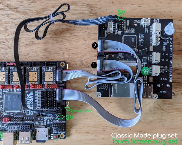
If you are using the SKR Pro V1.2, the installation instructions are here, .
Correct firmware for the SKR Pro V1.2 Lowrider 3 is here . You need to select “Show all 37 assets” ayt the bottom of the Asset List, then select V1CNC_SkrPro_DualLR_2209-2.1.1(1).zip Unzip it and put the .bin file on an SD card.
The installation instructions for the TFT are on the same page as the installation instructions for the SKR Pro V1.2, just scroll down a bit.
Correct firmware for the TFT is here. Select “Assets” on the most recent release (currently 3/9/23 Roll up) strong text then select the most recent zip file. Unzip it and put the contents on an SD card.
That is normal. After homing , Z = 200mm at the top of the travel. Later you need to move the Z axis so that it is just touching the top of your material, and then use the G92 Z0 command to set the Z=0 . This is because you could be cutting a variety of different thickness materials, and you want to start each job with Z=0 at the top surface of each material.
Note that you can also use the Probe command (G38.2 Z0) and the Tiny Touch Probe (sold separately) to move the Z axis to the ytop of the surfcae. If you do that, you need to change the G92 command to G92 Z0.5 to compensate for the thickness of the probe material.
Hope that helps you!
Cambie el firmware, pero ahora aparece “No Printer attached!”. Con la otra versión si me detectaba y podía mover los ejes. Que podrá ser?
The message should disappear after 15-20 seconds.
If not, ensure that the cables between the TFT and the SKR boards are correct (you were instructed to remove the grey cables to install the SKR firmware, so make sure you put them back afterwards).
I noticed that I didn’t attach a link to the TFT firmware in my initial reply (I have since added it).
Did you install both firmware (one for the SKR board and one for the TFT display)? You need to have both in order for them to talk proerly with each other.
The firmware V515 not working for my. I come back to V513 and now working. But still problem with Z when press homw button one of the Z motors still working. It continues to work when the endstop is pressed. And this happens randomly, it could be the right one, I unplug the motherboard, I plug it back in and now it’s the right one. And it also happened to me now that when I traveled the Y axis from the back to the home plate in the middle it stopped and I got this error “Printer halted. kill() called”. and it stopped.
This does sound like the endstops are incorrect. If the Z1 motor triggers the Z2 stop, the Z2 motor stops, and never triggers the Z1 stop, but if they both trigger close enough together, within the buffer of their normal deceleration, they’ll be fine.
You can test this by triggering the endstop with your finger while the machjne is still far from the endstop. If the correct motor stops, you have it right.
I thought about the same thing, I measured the distance at which the printed piece is from the edge and both have the same distance (I measured it with a foot of meter), when testing the Z endstops they are both pressed together and if I look at the plate the LEDs turn on they turn on. But the strangest thing is that, as I said previously, randomly, the right Z stops when it reaches the endstop and the left one continues rotating. I turn it off and on again and now it’s the other way around, the left one stops when I press the endstop and the right one continues to rotate. I don’t know what’s going on.
I managed to solve the z axis issue by changing the endstop z1 to z2 and z2 to z1 and now it works normally. Now I want to start seeing if my machine is squaring. But I have another problem and I don’t know if it’s normal or it just happens to me, being in the farthest part of my X and Y.Home when reaching the middle of my Y axis stops and throws an error that says the following “printer halted. kill() called” and the same with the X.
I think it only homes for a certain amount of cm before it decides something is off and stops.
Move the core closer to XY min before hitting home. ![]()
I think the problem that I get the error “printer halted. kill() called”, is because of the size of my lowraider3 in X 900 mm by Y 1250mm and having those measures maybe the V513 firmware version the measurements are shorter and that’s why I get the error. If anyone knows how to solve this porblema I would appreciate it if you could guide me.
I already told you. Move the core by hand closer to the endstops. ![]()
IIRC, the V1 firmware sets the bed size (and thereby maximum homing travel) at 600×600 mm.
- Either jog or move by hand the toolheat to within 600mm of the home position before homing.
- Edit the Marlin source code to set the bed size, recompile with VSCode, and install.
For me the first is actually pretty easy, since my CAM leaves the tool over the corner closest to home, almost always within homing range…
But I have the full machine bed defined in firmware, too, so take that for what it’s worth.
It’s true, you already told me
I would have liked to have been able to modify the size of the bed but I can’t modify that, much less compile it. Thank you.
In the Configuration.h file of the firmware, change:
- #define X_BED_SIZE xxxx//1220 // 200
- #define Y_BED_SIZE yyyy //2440 // 200
where xxxx and yyyy = the size of your table.
(located in // @section geometry)
Thanks Dan for your answer, I will see if I can modify it later. I have already measured the far corners of the lowrider and it is square. Could you help me with this: I want to make the struts but I don’t know how to use stlcam or how thick they should be or what material to use for this? Thanks.
The struts should be something reasonably stiff and stable. MDF or hardboard is generally recommended, up to 1/4" thick.
Take a look at the Estlcam basics documentation page. it’s best that you learn how to generate your own machine code, because you’ll be doing it for the rest of your projects.
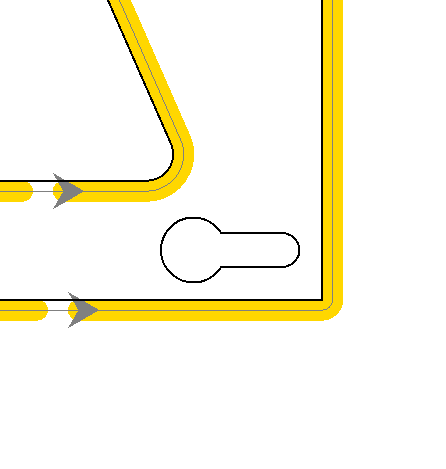
Thanks Dan, I was able to work on the estlcam, but I have a question regarding this part to get it to do the drilling in all its inner part? Could you help me?

You don’t really want to do that (at least it’s not recommended). The outer line should be cut as a part (cuts on the outside of the strut) to preserve the dimensions. The cutout triangles should be cut as a hole (cuts on the inside of the triangles) to preserve dimensions. The slotted holes should also be cut as holes (cuts on the inside of the slotted holes)) to preserve dimensions.


