Thanks Byron for your comments. I will keep your ideas in mind.
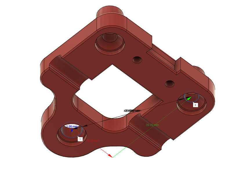
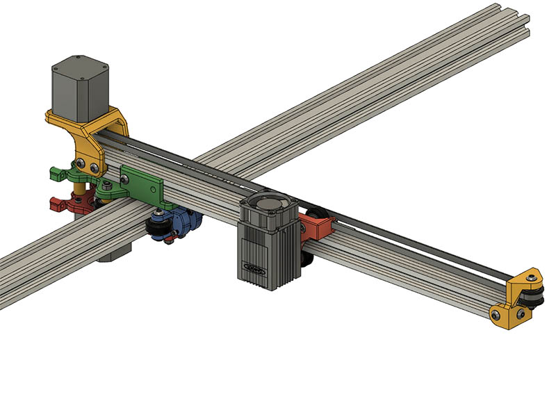
Did I download an earlier version of your laser carriage design? The M3 adjustment screw bottomed out and wheels were still loose against the V-slot. After it didn’t work for me, I decided to just make a simple one using an eccentric nut with the dimension 39.7mm between top & bottom wheel screws that openbuilds uses. I will just use wire ties to hold belt in place on carriage, but not sure it will work as is until I test assembly. I currently have it 9mm thick. Once I get the laser & piece this assembly together, some of these dimensions might change. I printed all the parts except for the legs to test assembly of the parts. Probably will do that tomorrow or maybe today. Here are a couple of screens shots with the dimensions shown.
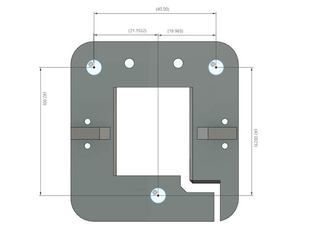
mmmmm… that 42mm between top and bottom wheel centres looks a bit bigger than mine, I measured mine at 37mm but I did use smaller wheels on my laser carriage than the XY carriage. The original design for the laser carriage, and the wheels, was borrowed from a kossel printer.
Actually 42mm sounds about right for 24mm dia vslot wheels… are you using v-slot or t-slot extrusion?
Your eccentric solution is a good idea…the original kossel design pre-dates eccentric bearings from open builds…
Yep, I am using 24mm dia V-slot wheels and V-slot extrusion. I will just stick with the eccentric solution. Weight wise, it is probably not much different.
One other thing I meant to ask you was the reason for the recessed washers on the wheel adjusters on the 2040, like this? The adjusters are the parts in blue for others not familiar with what I am referring to. Does it allow it to rotate easier while tightening?
The recesses are to allow you to put nuts on the bolts so you can tighten up on the bolt while leaving the adjusters freedom to rotate without excessive vertical play…or have I miss-understood you?
Nice drawings by the way!
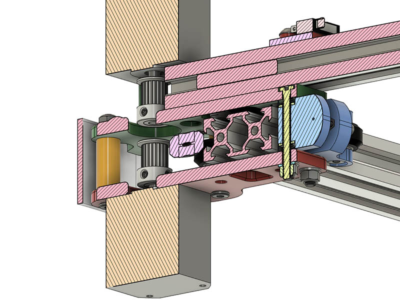
Ok, I had forgotten you were adding nuts to that part of the screw. I decided to go a little different route & make the plastic go full width between the lower & upper plate. I took out some of the plastic around those holes & they rotate enough to adjust the wheel tension. Here is what they look like now & the last screen image shows them assembled in place. They work pretty good & save on using 4 eccentric nuts. Thanks for that idea.
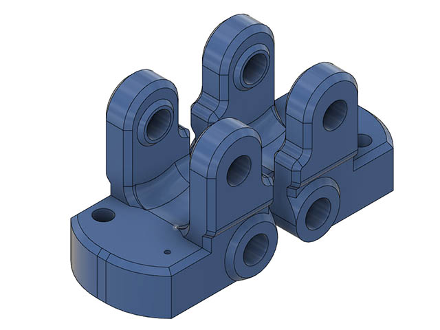
First test assembly yesterday went pretty good, but saw a couple of things I needed to adjust. I did not have any of the M5 ultra low profile heads for the length of 40mm to use with the wheel tighteners, but did have some button heads that were 2.8mm head height, so am changing that recess to 3mm for those.
I could not find my 20T timing pulleys, so decided to 3d print my own & match the diameter of the openbuilds idler pulley, so 32T matched that pretty close & also gets the belt closer to the laser carriage offset. I have to adjust the top plate a little as my M3 tightening screw & locknut hit the extended motor mount welds. Think I have the clearance for that correct now. I just realized the belt needs to stay within the V-slot with the way the Upper plate is attached to the V-Slot. I will have to reconsider that.
While checking for squareness of cantilever arm, my measurements were 416mm for one side of triangle & 414mm for other side when using a 450mm length 2020 & 250mm length 2040. That is only .48% off I believe which maybe good enough, but was thinking of way that I might be able to finetune that adjustment & came up with the idea of using 2-M3 tightening screws on the Wheel tighteners. This might not help with squaring the cantilever, but it does get the M3 screws further away from being in the way of the wheels if using a longer screw. My measuring was not perfect & will see if I can be more accurate with that for next assembly. In order to get those tighteners closer to 90 degrees of each other, I moved them in 1mm. The wheels on the tighteners are around 50mm apart, so I made the inside wheel holes 50mm which should also give it a little more support & not loose any more 2040 travel distance. Here is what the new assembly should look like.
I started tapping the M5 holes for the 500mm length of 2040 that will go in final assembly & will use that for the next test fit.
I decided to follow thru with my above belt version of this design and it looks pretty good to me. I will look it over some more before printing the parts. I took my carriage from the rolling plotter design as a starting point for that. I made the carriage a little thicker at 10mm since I needed to countersink the holes 4mm because the eccentric hole needs a washer added. If I get some of the openbuilds ultra low profile screws, I can cut at least another 1mm off that. I could also change the carriage to use M3 wheel adjustment that Mike was using to shave another 1mm off the thickness. Shouldn’t be much weight difference, so will leave that as is for now. I need to find my 20T timing pulleys. I should have 2 around here somewhere.
The top Green colored plate I have 2 side holes for t-nut screws on each side of 2020, but only think one is needed as I have two in the bottom 86mm apart. I have about 96mm overlap of the 2020 from 2040. I had about 62mm with the other layout.
Moving the carriage in the assembly, looks like I should have 300-320mm of cutting width with a 500mm length of 2020, so I have about 200mm less cutting width depending on length of the 2020 and a little over 400mm cutting length along a 500mm 2040 extrusion. This image shows a 1000mm length of 2040.
One thing I just noticed is I will loose a little bit of cutting width along the 2040 since I moved the wheels in back to 50mm spacing since they will hit the belt T-nut clamp unless I use some sort of belt clamp that is beyond the end of the 2040. Those wheels were 31mm apart in original design.
Don’t just rely on the front and rear rollers.
You should add one or more to the red and green pieces to hold the load. They should ride on and under the 20x40.
You have a lot of twisting force and just down force on the rollers you show.
ezcorer - The stepper motors provide quite a balancing weight behind the fulcrum and the twisting forces are very small in reality due to the minimal mass on the arm…this is not a Dewalt router hanging off the arm! None of the contemporary designs around the similar theme have any additional rollers to support the weight of the arm
geodave - you could just pass the drive belt through the leg and attach it on the outboard side…or make the 2040 10mm longer 
Thanks for responding to ezcorer. I figured you would be able to answer his concerns better than I.
You got me thinking about just making the 2040 a little longer. I can get a 600mm length of 2040 from zyltech for $5.95. That would give me enough cutting room & still not be too wide. I would like to come up with an alternative simple belt clamp. I searched for some ideas for this, but couldn’t find any designs that were simple. I am thinking an L-bracket something like this with another part to clamp the belt & adjust along the slotted connection. Might have to make the base of this thicker since I have to use further M5 hole to attach to it as the other hole is too close.
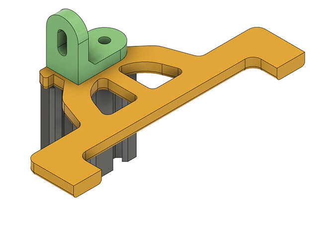
How about modifying the leg where the extrusion slot crosses with a serrated edge and a vertical clamp and two self tappers? I have never had to adjust the belt tension once set…the belt doesn’t stretch.
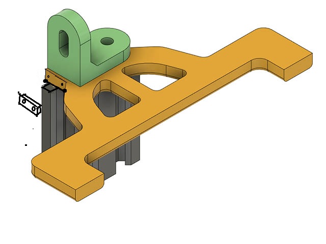
Sorry…my diagrams aren’t quite up to your standard!..but I’m sure you get the idea.
That is a nice simple idea. Your sketching is good considering you were editing a photo. Here is what I initially came up with for that, but realize it extends the width beyond the feet too much for me. I have a better idea that will just wrap the belt 90 to parallel with the feet & be able to clamp with a screw to tension it tight. I have not drawn that up yet.
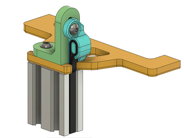
I had another thought on the cantilever idler end of changing the mounting location from below instead of above the idler. With the end screw & bottom T-nut screw seems like it should be sufficient support. Here is the above versus the below design. It has 1 less T-mount screw & changed M5x30 idler screw to M5x25mm. Probably could change the original to M5x25mm by changing that 3mm spacer to 1mm washer after looking at location of belt.
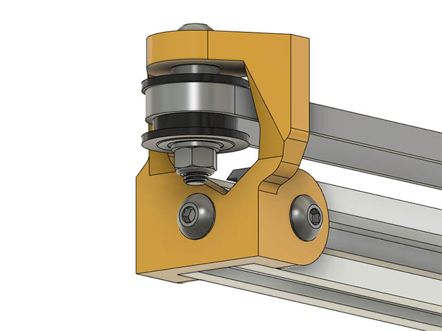
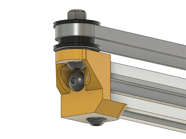
The bottom mounted version looks much stronger to me, also I don’t think you really need the end 5mm bolt if you add some blocks to the sides that fit in the extrusion grooves.
(since you very kindly said you thought my edits are not too shabby…here is another) 
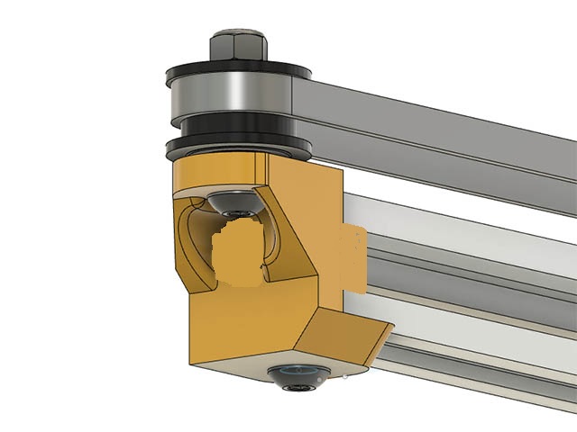
Ok thanks, I will change that & try it. That makes sense since it will be pulled against the end of the 2020 with the belt tightened. I have my new upper & lower plates printed. I printed them with 5 perimeters & 50% gyroid & they will quite solid. I will print the new motor mount & idler mount before test assembling it. I might change my laser carriage a little before printing that.
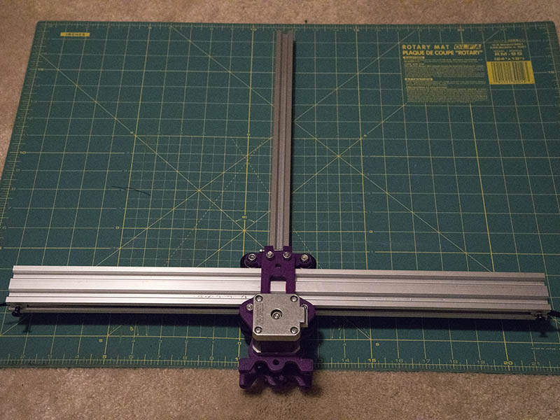
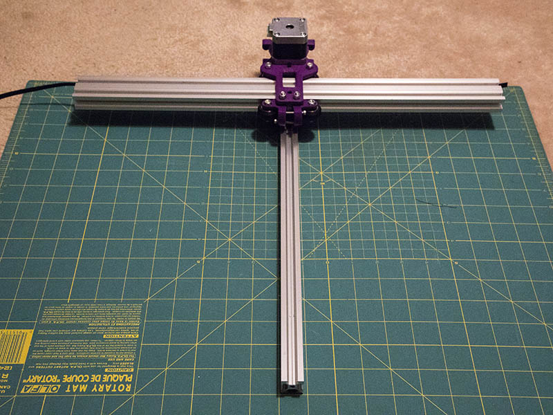
I test fitted the upper & lower 2040/2020 mounts this morning & they are visually out of square. The best way I could see this visually was to lay them out on a cutting mat. Mike, did you have any problem adjusting this to square? I was thinking the M3 screw adjustments on both wheel adjusters would help with squaring this up, but maybe that was not a good idea. The M3 locknuts are recessed on the inside of those wheel adjusters. I wonder if making them captive nut slots would help. I could try making these plates use eccentric nuts and see if that helps, but since Mike got this to work seems like it should be adjustable somehow.
I didn’t have a problem with the arm not being square to the beam.
Leaving aside the straightness of the arm extrusion, if it is out of square the only thing it can be realistically is a difference in the hole positions of the two rear wheels, the adjuster wheels will just remove play, not hold it square. could you fit an eccentric to one of the rear wheel holes?
Did you check the upper bracket for burrs or blobs from the printing?
It doesn’t look a huge amount out of square, how tight a fit is the arm in the upper frame… could it be shimmed?
What would be a reasonable level of accuracy from a plastic bracket? Perhaps the placement of the hole in the upper bracket weakens it? Perhaps try swapping the wheels around to see if the error moves?
I had a thought while at breakfast this morning to leave the bottom t-nut screws loose & see if I could square it & then tighten them since there is a slight play there, but it didn’t buy me anything. Since I had the side holes for 4 T-nut screws I tried tightening them 1st before tightening bottom screws, but not much if any change there either. The eccentric in a rear wheel sounds promising. I will have to drill the hole out slightly to accommodate that on both the bottom & top plate.
On the bright side, looks like I have 16" of movement along the 2040 axis with your t-nut belt clamp which is sufficient for me. If the eccentric on the rear wheel does not work, I might change the front wheels to just use eccentrics and widen the base to 60mm between holes which would still give me 15" or so work area. I will double check all my dimensions first to see if I missed something. I could always cut the bottom plate out of acrylic or aluminum for a stable mount, but don’t want to go to that much trouble if not needed. I will also 3d print a calibration print to see if something is out of wack there that I missed.
I checked all the dimensions related to wheels & V-slot & top 2020 connection side mount & those look correct.
Looks like the eccentric on one of the rear wheels fixed it. Thanks Mike.
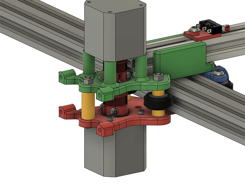
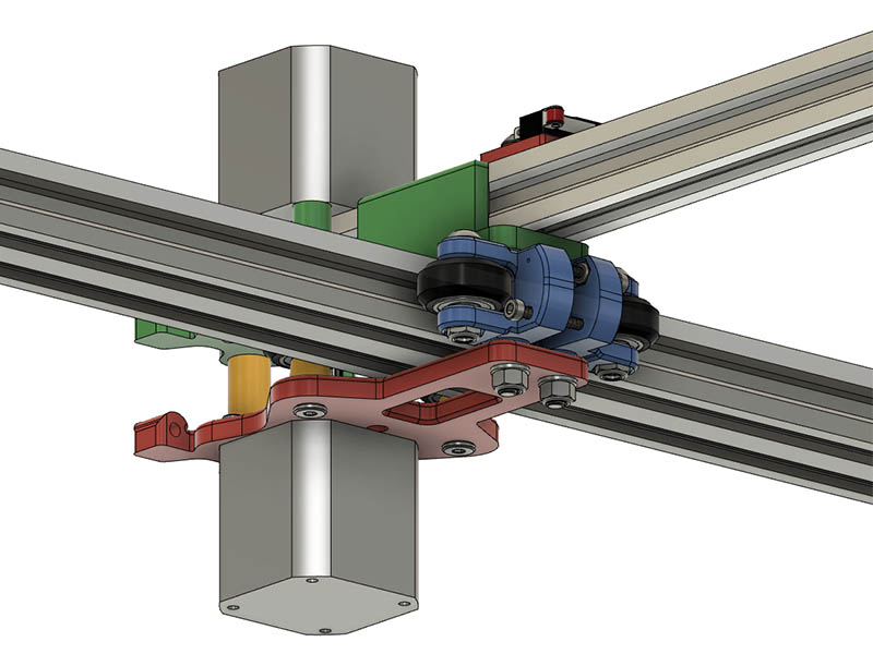
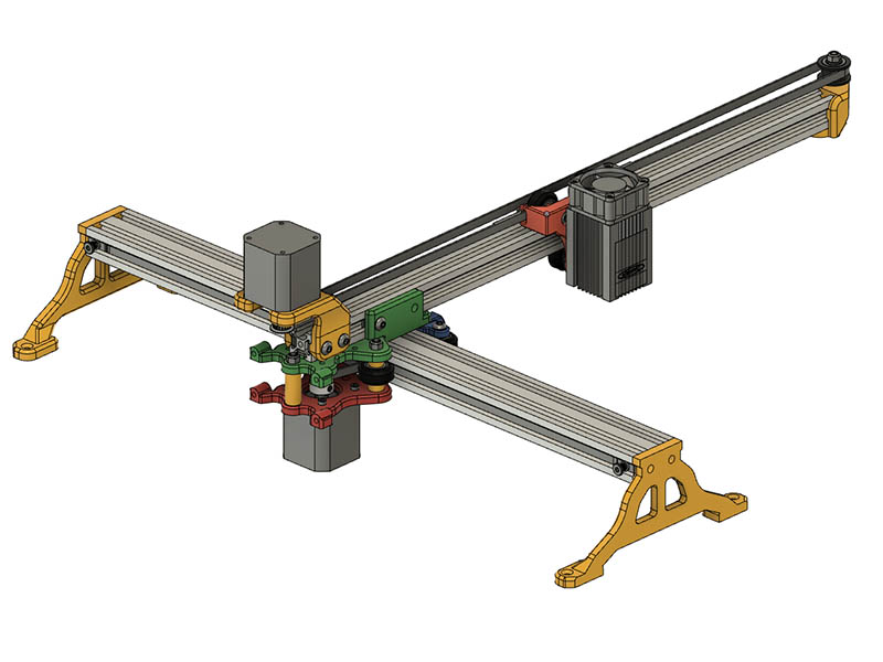
I am assembling all the parts now that all the current problems have been worked out with Mike’s help. I just have to finish printing the laser carriage & the 2 feet. Should be able to finish assembling it tomorrow except for no laser or electronics board yet. I have both motors on there now & they do give it a hefty counterbalance. Here is what the assembly drawing currently looks like.
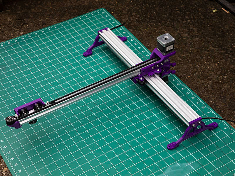
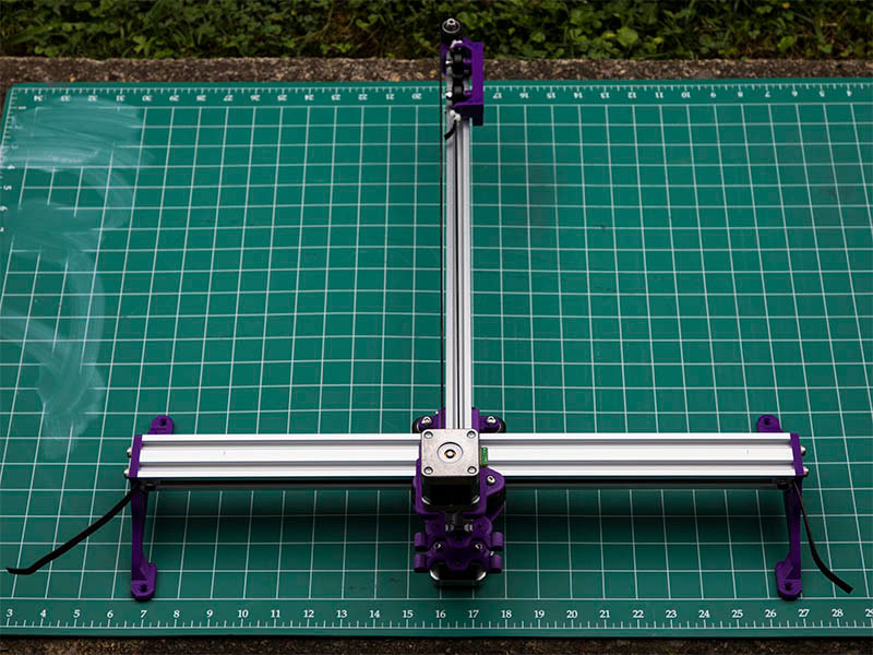
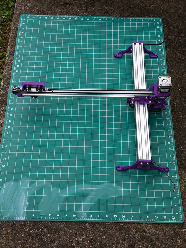
I put together the 1st full mechanical assembly of this design. In current configuration with 500mm 2040 & 2020 it weighs in at 3lbs 11.2oz. The belt connection for the laser carriage was 2-3mm out of alignment with belt, so am reprinting that part. I have about 16"x12.5" (406mmx317mm) working area. My bottom motor is 40mm thick & has about 4-5mm clearance from working surface. This could also be another pen plotter. Here are some photos.
