It does not really show on the bag the resistors came in, but based on your photo they probably are 1/4 watt. Thanks for the clarification.
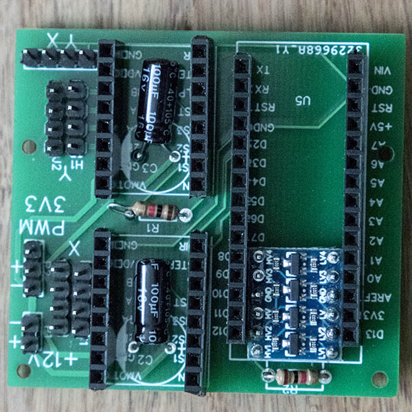
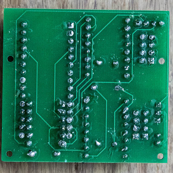
Here is my first custom board all soldered up. I have not tested it yet, but solder joints look good enough to me.
I am starting to get interested in trying my hand at Surface mount soldering & came across this practice kit. What else would I need besides a small solder tip & good magnifying glasses? Would I need some sort of hot air gun? I have a good circuit board holder. https://www.aliexpress.com/item/4001189711627.html
1 Like
You can put your multimeter on the ohm meter setting, and they usually have a beep mode where it just beeps if there is continuity. Before attaching all the chips, it is a good idea to use that to make sure there aren’t any shorts between pins that you don’t expect. It looks good from the pictures though. Fine tips on your meter leads is a great way to spend $10.
I enjoy soldering and I have tried to make it easy for me to do all kinds of soldering that I can at home, without spending $500 on gear.
This is the solder station I have. It is currently unavailable, but you really don’t need something fancy: Zeny® 3in1 SMD DC Power Supply Hot Air Iron Gun Rework Soldering Station Welder 853D . Here are the extra tips I have: https://www.amazon.com/gp/product/B007YU2EQ2/ref=ppx_yo_dt_b_search_asin_title?ie=UTF8&psc=1. The most important is temperature control. Then I’d say the fact that it is a wand and not some larger self contained thing is really helpful. I almost never use the hot air. It has a good chance of ruining the neighboring parts. This was about $100 when I bought it. I use the stand from my old iron. I haven’t ever used this blue one.
The solder is really important too. This spool will last a decade, but the solder is nice and the diameter is small, which really helps put just the right amount of solder down: https://www.amazon.com/gp/product/B004L4VHJE/ref=ppx_yo_dt_b_search_asin_title?ie=UTF8&psc=1
A solder sucker is useful for rework when you are doing through hole soldering: https://www.amazon.com/gp/product/B0002KRAAG/ref=ppx_yo_dt_b_search_asin_title?ie=UTF8&psc=1. Solder wick and flux are also essential for rework and surface stuff especially. Then to clean up the flux, you need isopropal alcohol.
Solder paste can be useful for smd too. But I find the tiny solder is easy enough that I rarely use it.
Some flush trim cutters are really useful too. If you need to take out one of those rows of 10 pins, it is easier to cut them first down to 2-3 pin chunks and desolder them separately.
I was really surprised when I got magnification for my eyes to find out that my hands are actually much more controlled than I thought. Once I had a magnifying glass, my hand-eye coordination went way up. My old work literally had a magnifying glass and I was much better using that than I am using the magnifying goggles I have now.
A set of tweezers that can pick up the tiny parts and are offset so you can hold them at an angle help with tiny parts.
If you are designing your own boards, make the pads for resistors and capacitors too big. Putting a 0805 pad down for a 0603 resistor is fine, and gives you more room for error.
I’ve never tried the method where you use an oven.
2 Likes
Thanks for the detailed info. I have this pretty good soldering station I bought a couple of years ago. They have gone up in price since i bought it. 21-10115 - Tenma - Soldering Station, 110 VAC, 896 °F (newark.com)
I also have a 1.6mm, 2mm & 3mm chisel point soldering tips. I probably should get a smaller tip. I have been starting to think about switching to a lead free or silver solder. After watching the fictional series Halt and Catch Fire on Netflix where one guy started to have some health issues from so many years of soldering. Even though that was a fictional series & I would not be doing much soldering, this seems like a good thing to switch from if possible. I have a pretty good size roll of silver solder, but it is too thick a diameter for this work. Here is a 2020 video I found comparing 3 solder types which seems informative. What are your thoughts on these alternative solders?
Lead solder vs lead-free solder vs silver solder - YouTube
The iron looks good.
I haven’t tried other solder types. I should probably get one of this little filter fan things. Lead never leaves your brain.

It may never leave your brain but it sure does make a better solder than the lead-free stuff, especially when trying to lead-free solder something previously soldered with leaded solder. I have an 898D rework station. While placing a component with the iron, I normally use the hot air gun afterwards as it heats up both ends and allows the components to self centre due to surface tension, it also neatens up the soldering by removing any blobs that might be left over from the iron,this only works for boards with components on ONE side only  . Horses for courses again!
Spending your money again Dave but a microscope is very helpful in part identification and checking for shorts/dry joints…
Sometimes you can cheat if the SMD parts are just too small for your soldering skill level…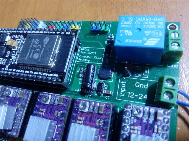
1 Like
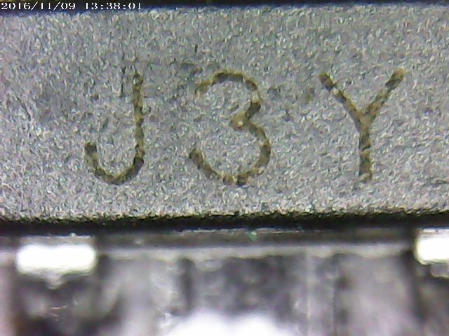
I did get this microscope that I referenced earlier in this thread with that same 1000x & find that magnification too much for viewing circuit boards.
You can reduce the magnification by moving the microscope further away from the object…
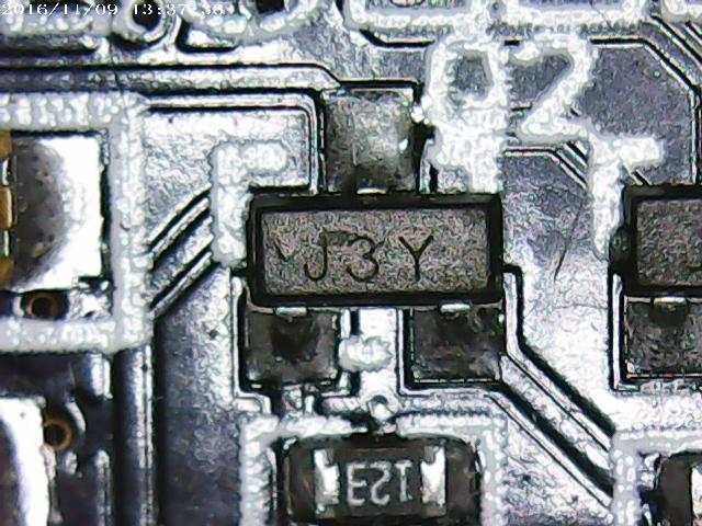
Same chip, just bigger…
2 Likes
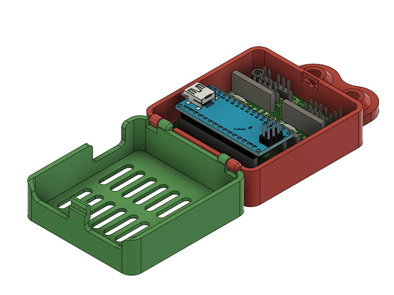
I am starting to get back to this machine now that weather is starting to warm up more. I made a hinged case for the small custom grbl board that Mike designed. I like to use locknuts with the mounting screws. This board is sized for M2 screws which I do not have, so I drilled out 2 of the holes that were far enough away from the traces to 3mm holes & made 2mm size posts in the case for the other 2 holes. 1st test print seemed like it work good, but beefed up the clasp on my 2nd print. I had redrawn this pi zero hinged case a while back in openscad for better clearance & used that design as a starting template for this design. https://www.thingiverse.com/thing:1595429
Here is a screen shot of the case.
4 Likes
I made one these hinge case designs for the EleksMaker Mana 3 Axis controller if anyone wants to try it, I will upload it here. I will probably eventually make another one or 2 & put them all on thingiverse. I didn’t get a chance to print this one yet & added nut traps to this version. Print size is about 175x97x20mm.

I am a high school teacher running a makers class. One of my students, at my suggestion, is working on building this well-designed machine. The build side is completed and it looks great. We have been experiencing some problems with the g-code and getting the stepper motors to respond.
We have successfully uploaded grbl to the Nano, but are unable to get anything beyond a short twitch out of the stepper motors. Any advice or help would be appreciated.
For my own understanding, the Arduino Nano with stepper motor shield is sufficient to run the device, correct? There is no direct need for the Raspberry Pi as shown in the initial build plans.
1 Like
The Nano running the grbl software will control the machine movement when it receives gcode commands, but you’ll need something sending gcode to the Nano. The raspberry pi did this in the original configuration, but you could connect the usb of the nano to a computer running something like repetier host or universal gcode sender (UGS).
Other controller/firmware combos support a display and sd card so you can print without a connected computer, but I don’t believe the nano can run such a display. Here again, the raspberry pi provided this functionality on the original design, most likely through a wifi web interface rather than an embedded display.
2 Likes
The nano sends some simple digital signals to the driver. If you want to make sure it is sending the right thing, then you can look with a multimeter or an oscilliscope at the interface between the nano and the driver.
Enable turns the driver on or off. Some of the drivers have this reversed, so a voltage at ground means that it is enabled. If it is enabled, then the stepper position will be held, even if it isn’t moving.
DIR sets which direction to move. If you change directions, you should see this change, but otherwise should be constant.
STEP goes up and down to move the stepper. Each pulse is one microstep. It is harder to see on a multimeter, but if the voltage is high or low and then goes a little bonkers, staying somewhere in the middle when moving, then that is probably right.
The drivers need something like 12V in Vmot.
If all that works, then you might have the motors wired wrong. Or there is a loose wire.
The drivers (like drv8825s) need to have their current set with the little potentiometer on the top. Polulu has a decent video for setting it. 0.7V is a good all around starting position for most drivers and motors, but I know Tom cringes when I simplify it like that :). Definitely don’t use your motor’s max current rating or you will cook some stuff.
Lastly, you might try swapping the drivers. They can be shorted or something and they might just need to be replaced.
1 Like
@KirkKhronicles. You have installed the GRBL firmware on your Nano. As @ttraband says, it sounds like you are missing the software to act as a Gcode sender. The fact that the steppers kick at all is a good sign that the Nano is working and the steppers are ready to go. What flavour of computer do you have to hand? (PC, Mac, Pi etc) If it is a PC I would recommend LaserGRBL software, connected via USB to the Nano, but there is other excellent free software gcode sender software available… you might need to install the correct drivers for the Nano (it depends on which serial to usb chip the Nano has…you may need to install a CH340 driver on the PC so the Nano shows up as a serial port). Let us know of any developments!
You may be interested in the original build thread.
1 Like
I ended up not using the raspberry Pi after all & just used a laptop to connect to the controller. I used openbuilds control software on a laptop mentioned earlier in this thread to connect. I believe others have answered your other questions better than I could.
Thank you all for the quick reply.
Yes, we successfully flashed the GRBL firmware to the Nano. We kept it connected to a PC and used the Universal Gcode Sender there to try and move the axes to confirm the motors worked. This is where we had the problems.
In my own research to troubleshoot the issue I also came across those videos from Polulu. I will get my student on those adjustments today, multimeter in hand. We will double-check the Nano, the port/serial identifier, drivers, and have another go. We do have some extra driver modules and are using the three-axis Nano stepper motor shield.
Thank you very much for the link to the original build. It is our plan to have the laser engraver separate from a PC. The Raspberry Pi functioning as the controller with internet upload abilities for files is our goal. I can direct my student there for additional information.
I really appreciate everyone’s help.
Be aware that different manufacturers of clone A4988 stepper drivers use different sensing resistors which lead to different vRef readings for a given target current. Stepper VREF calculator helped me identify the sense resistors on my boards and properly tune them. Watching that polulu video had me set my clones way too high, leading to heat issues and stuttering. Not that their method is wrong in the video, it just didn’t cover the cheap parts I’d purchased.
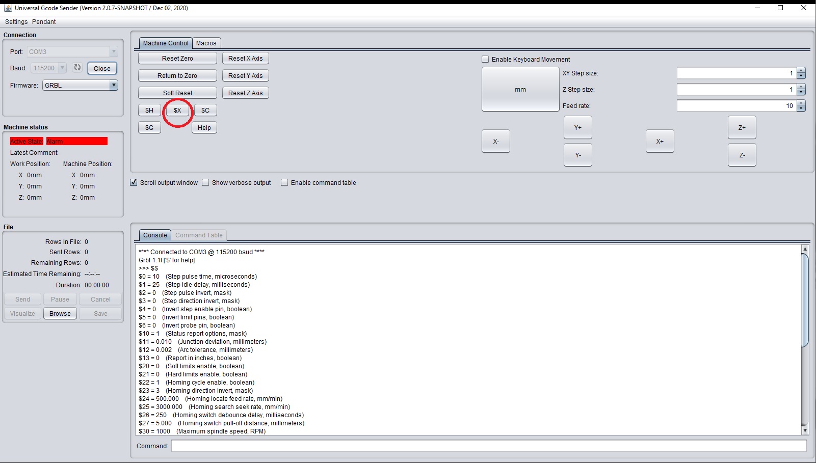
One simple issue you might not be aware of is that you will have to send either $X to unlock GRBL or, if homing is enabled ( if $21 = 1) you can use $H to home your machine and unlock GRBL. In UGS you should be able to see your controllers GRBL settings in the console window once you are connected to your controller. (select the correct com port and try 115200 baud first.) If you can see that you will notice there is a Alarm status in red, clicking on the $X button should clear that and allow you to use the jog buttons to move your axis’
And a final thought that may or may not be relevant… You do have to have a separate 12V supply connected to the shield, the current and voltage going to run the Nano doesn’t provide anything for the motors themselves.
1 Like