Love new ideas and constructive criticism. Hardly seems like arguing your position. You know to get the ideas in before I get to far and if I am talking about it publicly you know I am making progress and there is little time left for changes.
AND…if it happens to be rugged enough it might just be a good platform to start a new printer from…a little two for one engineering.
Sorry for all the tangential talk Dan…I need to be more mindful and make some new topics. I have been doing this a lot lately.
Yes. It works on my grid bot. The key, I think, is to make it home where the belts between the motor and the gantry is smallest. You don’t want it stretching the belt any. It is loud though.
One of my reasons for building the ZenXY was because I intend for my next printer design to be CoreXY based. My current one was based around leadscrew motion, since I (erroneously) attributed the complete crap quality of my first 3D printer to the belt drive for the X and Y rails. (It is true that the belt drive for that printer was irredeemable crap, in my defense.) And while am still quite happy with the print quality of the leadscrew driven axes of my printer, now I’m looking for speed and accuracy… And something interesting and new. I’m sure that I can get the speed and accuracy (now) from cartesian kinematics, but I want to stretch to something new with the CoreXY kinematics. Building the Zen table without the complication of a Z axis seemed a good way to start. There are many elements of the design that I fully intend to steal, primarily the belt arrangement at the back of the mechanism.
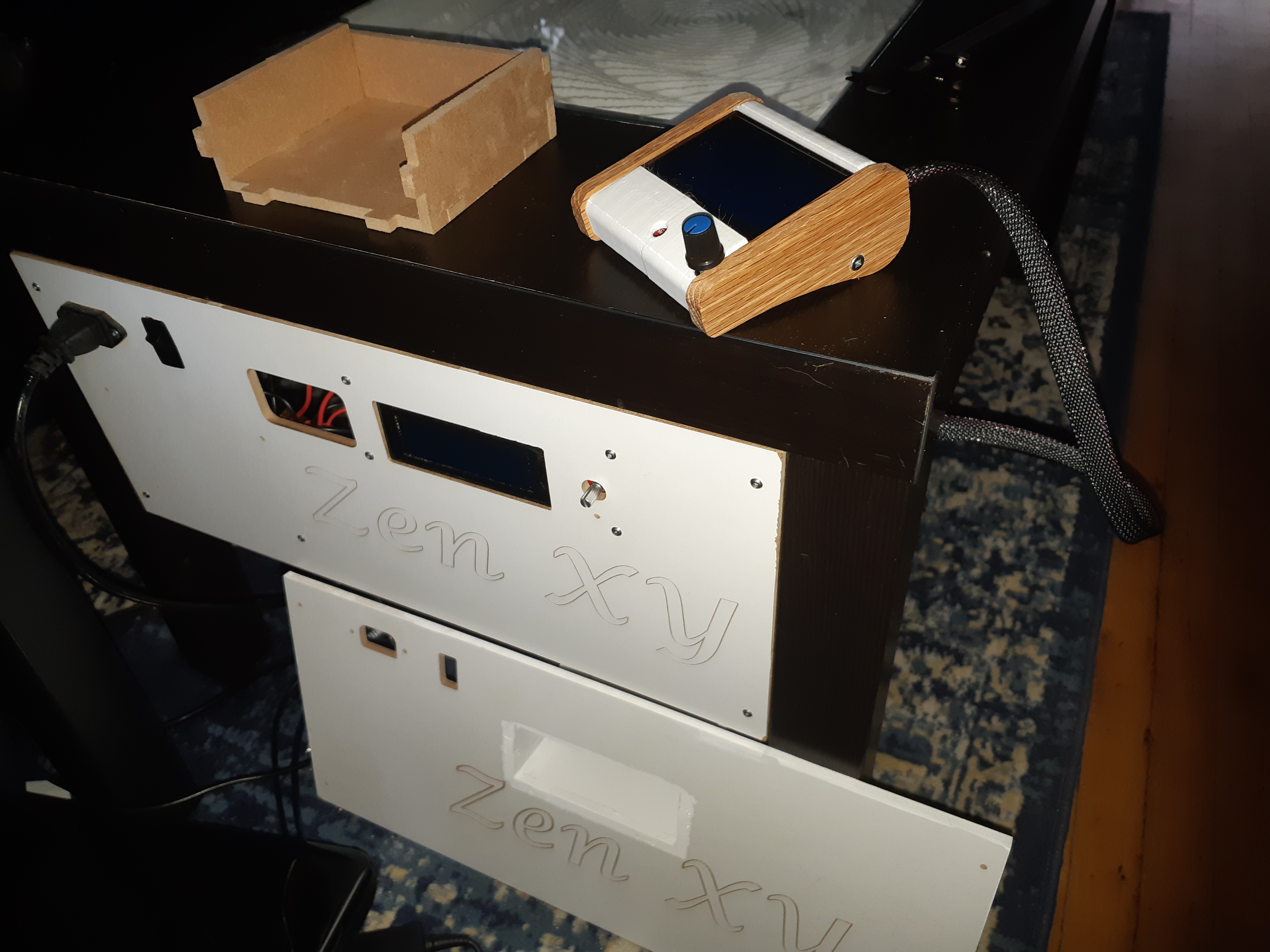
In on topic news, I received my goodie bag, and have swapped in the 12864 display for the 2004 display. Compiling the firmware was a PITA, since I could not get it to do so on my Windows laptop. Apparently the command line gets too long for the final link. I made a live flash drive image for my laptop, installed the Arduino IDE, then insgtalled the u8glib library into that, and then compiled the reverted Marlin firmware for the ZenXY with the 2004 display customization reverted back to the 12864 display.
I cut a new end plate for the power socket and IO, since I no longer want to have the 2004 display embedded in the table end. Instead there is a 45mm by 110mm pocket cut into the plate that will house the 12864 display with the 2.5d case. (The sizing prototype is on the table next to the display, I made it 1/4" too short.) I’ll be replacing the old piece today.
The new center piece is now loose. It was okay, then I sent a print job to it. It got caught up (I’m 90% sure that it’s the belt that goes from motor to corner causing the jam) Yanked itself out of square, with the belt slipping in the zip tie, and now the center is loose. The exact same print job worked not 12 hours ago without a hitch. 2 new scores in the same X rail as before, in line with the motor side bearings.
I replaced the bearing spacer with the thinner version, which seemed to work. It wasn’t jumping on the rails, but it still managed to catch somewhere. I can’t find any damage on the belt. I thought that the belt might have developed a spur somewhere that’s catching on the bearings, but I can’t find it. I have to cut the zip tie again to put it back in square, because as soon as it’s out of square the belt gets caught everywhere, as I suppose makes sense. It sure doesn’t make it better.
Okay. I’ll do that as soon as a new center is finished printing. Once it’s loose and moving around, I have no other way to make it tight again.
The observations that I had before: If I’m under the table when it starts (No alcohol involved, thanks) watching, and I hear it start to bind, it stops immediately if I touch the belts that run along the top of the rails, flattening them between the trucks and the back corners. Sometimes it takes a while to start up after I release them. This is what caused me to suspect the spacers, and make new, thinner ones. I pulled the OD of the spacers down from 12mm to 9.7mm. This seemed to help, but once it caught, it was caught.
It may be worse by running the table at higher speed, but I’m not seeing the belts go slack at any point. I do run top speeds that are faster than I have ever tried to run a printer at. I feel though that it ought to work. Might be that I’m making a small problem bigger, of course.
I don’t think it is constrained nearly enough for those types of speeds. I made it for slow (what I was hoping would be quiet) Zen speeds. You start whipping it around and it will jump up on the rails.
That is why that one was never even attempted to be a printer base.
Some of the fastest printers that I’ve seen use CoreXY kinematics. I can see that I was definitely overreaching.
So I’d been running things at 200mm/s (12000mm/min) Actually it mostly does okay at those speeds, and I’d be willing to bet that I could use nearly the same mechanism and get it to be okay.
At 100mm/s, it doesn’t jump as much, except on some abrupt direction changes, where I start pushing the jerk settings in the firmware.
80mm/s seems to be where the issues settle out, but a full table pattern takes so long.
I’ve done martial arts most of my life. I guess I do “Speed Zen”.
(edited above to include missing zeroes)
@jeffeb3 there’s a plugin for Octoprint that I downloaded today called Arc Welder. It’s supposed to take a bunch of G0/G1 commands and “weld” them into G2/G3 commands. It looked really promising, but doesn’t seem to work on Sandify output. I was sad. Not sure why it doesn’t work. The plugin is in the Github Repository. Even at 8mm/s, there are times when I am overloading the ability of Octoprint to send gcode to the table at 57600bps. Or maybe it’s the poor little Arduino that can’t process it that fast.
It cant take a while. But isn’t the journey part of the fun?
57.6k is pretty slow. Is there a reason you can’t use 250k?
I saw the arc welder. I thought it would work. I will have to try it.
Sandify’s core function, taking a shape and transforming it, should allow curves in the core shape, and then transform them like lines. The kernel shapes need to be drawn using curves where appropriate, and then all the components need to be updated to handle curves along the way. Then the output needs to have the right curves in the output. It is hard to be motivated to do all of that, when it doesn’t look any prettier.
Having a solution that can operate on the final points and create arcs from the xy points would be great.
I was having trouble at 250k… But I see when I reloaded the firmware for the 12864 display, I set it back. Doesn’t seem to be any faster though. It still gets bogged down in some of the curves.
I totally get what you’re talking about re-coding something that doesn’t look nicer when it’s done. I’d be loathe to do it too. I had some high hopes for Arc Welder, but it keeps saying “0 arcs generated.” and doesn’t affect the gcode at all. It seems to be trying, but something in there doesn’t seem to be ticking the right boxes.
I guess there are two other reasons I run it slow besides sound. The first would be it can lose the ball in deep powder and the second is it kind of splashes the design. Slow leaves behind super sharp peaks.
Odd that the problem isn’t just jumping out though. Such few parts…and why does your center keep getting loose. I can’t figure a solution to fix everything at once. Have you ran a print test to see if maybe your printer is off or anything, if the rollers are bigger than normal the tubes would be further apart and the belts would be tighter under the spacers (honestly a small amount though). https://www.prusaprinters.org/prints/36412-xy-size-and-square-calibration-print
I think this thread is my main motivator to go work on the new zen, drives me nuts when there are weird issues like this.
Well, I seldom lose the ball with the magnet properly shimmed. Sometimes when homing and it goes across at Y=0, where the magnet centre is under the very edge of the table. I take care of that with the start code:
G28
G1 Y7
G1 X340 F4800
G1 X0
G28
This ends up with the machine homed and a default travel speed set. If I lost the ball on the first homing, it ends up getting picked up.
I have a print file that runs around the perimeter as well. I lost the ball more often I first set up the machine, always around the perimeter, usually at X=0 or Y=0. Even commanded to high speeds, it still ends up going quite slowly in the center of certain shapes, and I don’t think that I lose too much sharpness on the ridges… But it’s probably non zero. I guess though I’d rather have the option.
The new center is behaving very well at the lower speeds, but the belt still seems to want to catch every now and again. I think I’d feel confident at the lower speed in turning the motor current down again. It’s probably too much motor power that was hammering the center into being loose. I can’t get a good photo of it, but I can see where the holes for the bearings were getting the threads from the bolts hammered into them. I think a tiny bit of well-placed epoxy could permanently resolve it, but then I’d probably never get my bearings back if it wasn’t quite enough.
Considering that what I mostly want is a project to tinker with, I’ll fiddle with stuff. I do want to figure out a set of printer kinematics out of this, so the more I understand about how to make this fool-proof, the better. I’d like to see if I can really get this thing moving, having perimeter moves, particularly repeated perimeter moves going much faster is appealing. I think the trick to not losing the ball is acceleration and deceleration.
While working on this today, I left an allen wrench on top of the glass… It was interesting to see that when the ball passed under it, the wrench would turn and move around to follow the magnets under the table.
@jeffeb3 I think I understand why Arc Welder doesn’t work on Sandify output. Sandify isn’t outputting segmented arcs, it’s outputting segmented spirals. The radius is constantly shifting, which doesn’t give Arc Welder anything useful to do.
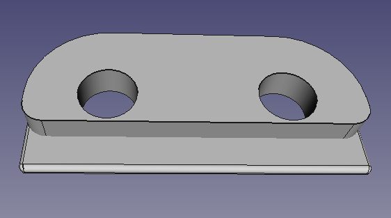
I was working on a design which moved the belt through the tube to avoid the problems that I’ve been having. It seems that even my reprinted spacers were still allowing the belt to get caught under the rollers, so I tried a different approach.
This is a little file that I designed in FreeCAD to replace the spacers. Printed in pairs, the holes through are 25mm apart, to fit the rollers on the ZenXY. The rounded top is just a little bigger than the 608 bearings, and the bottom is 9.5mm from the hole centers. This makes it about 1.5mm shorter than the 608 bearings, and gives enough space for the tube without friction, but not enough space for the belt to get caught. The FreeCAD project and STL are here: ZenXYBeltGuard.zip (77.7 KB)
I don’t know that this is a solution, but so far, I’m 45 minutes into a print and I haven’t heard it jump yet. I get the feeling that if it does though it’ll be a doozy. I’ll still call it a band-aid, but so far, it seems to be one that works.
I’ve ordered another LACK table. I think I have a few improvements to the table. I’m not going to cut out and replace the bottom, instead I’m going to see if I can surface it to remove the glue, and maybe shave it down to be a little thinner. This will mean that there is practically zero variance in the bottom height, so with good printed pieces, there should be no way for hte magnet to be wrong. This does mean though that I’m not controlling the sandbox position from the underside, so it may be difficult to drill pilot holes for the plastic pieces. I think that what I’ll do instead is CNC cut jigs to hold the Y rails in place while the pieces are screwed to the bottom so that they have to be in the correct location.
You might be right about the spirals. I’m not sure how their fitting works, but the spiral nature should be possible to replicate with a different offset for partial arcs. At least to some degree of error.
You (or I could, I guess) could try a circle, but check the button to retain the shape. That would make a lot of perfect circles.
I hadn’t played with that setting… And it doesn’t help. Still zero arcs created, so that’s not it. It has a resolution setting, where it will not create arcs if the tolerance is more than 0.5 times the resolution. By default that’s 0.05mm, so if the X/Y of the arc varies from it’s calculated by more that 0.025mm, it will keep the line segments…
Nope… Even bumping that up to a number that would make some very inaccurate guesses doesn’t do it, so there’s something else going on there.
I’m re-doing the mechanism to remove the quarter inch that I don’t need in X and Y.
Since I’m not going to take the table apart and put it back on the CNC I wanted a method to ensure that the rails will remain parallel.
I measured the distance between rails very carefully, and subtracted 6mm. Then I cut a 2 piece jig to hold the rails 495mm apart, center to center from some scrap 1/2" MDF. This time I’m less concerned with the hole placement relative to the part. I’ll hold the tube in the correct relative placement and just screw it into the table. This is (to me) a much less repeatable experience, and not the way I’d like to do it, but it should still result in vert precise rails.
I also cut a new left rail from my dwindling stock of leftover steel, to get rid of the piece that has the bend in it. I have to roll the steel on a very flat surface and watch very carefully in order to be able to even find that bend, but the new rail doesn’t have it.
My plan is just to break the MDF below the steel and pull the jig out once the parts are screwed in. I sawed part way through the MDF to make that easy.
Well, surprising to nearly nobody, I did something weird. Somehow when I removed a quarter inch of X I ended up with a belt path slightly longer than when I started. I think I somehow extended the Y axis.
It’s all okay, I managed to make the belt pathing work, and seem to have discovered an error with the previous setup. The motor mounts were sagging slightly, which allowed the Y axis to come a little further apart at the low end of the axis. It did not do this constantly, and it was a small movement, but resulted in couple mm of drift in the axis.
I added additional clamps to hold the motors up at the correct height.
So now the rails are perfectly parallel, and remain so under load and strain. There’s a bit of weirdness still because one of the mounting feet for a corner broke while I was re-doing the belt. I needed to re-do all of my Sandify patterns to account for a new minimum and maximum X and Y parameter. I’m running everything MUCH slower.
I can also confirm that what happens when the belt gets caught like that is the motor skipping stepps hammers the threads of the bolt into the printed plastic. Specifically into the piece that holds the spacer where the belt ends are tied.
You can see where the threads are intentrd into the plastic here. This is NOT subtle when in place it allows a lot of movement between the rails.
Currently, I sometimes get a bearing squealing in Y movement. I think I need small washers in addition to my solid spacers. Maybe I could go back to regular spacers, but these still seem like a good idea to me.
Turn your drivers down a lot further. You much rather it skips steps than rip itself apart right? There is little to no forces normally so any issues must still be there.