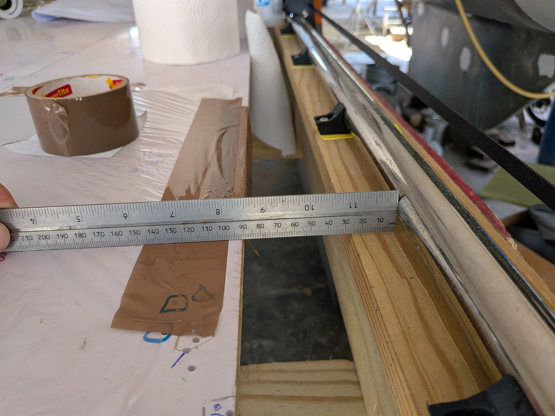
Not sure if this is troubleshooting – if so, it’s troubleshooting for the documentation…
So there is a LOT going on when you do the build. I finished my build though and I got the rails mounted. I chose to do a 4x8 foot build. I bought my metal to match the calculator. I got it all setup and found on the non-metal tube side I couldn’t get to the table edge. And on the metal tube side, I could get off the edge of my table.
It’s not that big a deal but I’m surprised we don’t have some kind of 3d printed gauge that indicates where to offset the tube rail from the cutting table so you know here to put things. Or at least bring it up in the docs.
Again, not a huge deal but it was confusing. Maybe I messed up somewhere? There is a lot going on. It’s not that hard to fix. And in hindsight, of course I shouldn’t be surprised because I could have moved the head to one side and observed the difference but… I was surprised.
I forgot to try to convey how excited and happy I am with the build. So far, this thing is amazing. And I’m looking forward to posting what I’m building with it and my build in general. Just figured I should mention that as overall I’m very happy.
This is one of the things that is most needed, and it’s the most difficult to do for those of us who have seen the machines and the builds for a long time.
Feedback- and in particular suggestions for improvement- are welcomed.
That’s been suggested a time or two along the way. Do you have a mock up or even a description of how you might make one?
Or maybe our docs are not clear enough.
What size cutting area (actual dimensions ) were you intending to build? What values did you put into the calculator? What size did you build your table to? What lengths did you cut your EMT to?
(Not implying you were wrong either with your build or with the calculator; these would let us use the same numbers and see if something is amiss)
I’m not sure I follow that completely. Have some pictures to share of your build and how things aren’t quite as you expected? PIctures > 1000 words and all that…
We love it when community members post details of their builds, their projects, and super importantly: Their struggles.
I guarantee that every thing one of us struggles with and talks about there are many others silently facing the same issues and just not piping up.
So the part I was confused about is basically the offset on this side from the rail determines how close to the edge of your table the bit can get. Also there is the offset along Y – the negative offset off the top of the table that would determine where that end stop should go so you can get to Y=0 and that is edge of the table (I can go past Y=0 but on the other end, I’m maxing out before I get to the end of the 8 foot sheet).
Does that make sense? It’s not a big deal I just didn’t think about it or have an idea of how to figure out where to put things to get the whole sheet. I’m going to replace the current spoil board with some MDF and I can shift over the whole table top at that point as my X axis is just a little off. For Y, I’ll check but I can probably shift the rail further in the Y+ direction. I cut one of the long belts slightly too short so going to hold off on that until I get a replacement belt.
So not a big deal at all and maybe the build directions mention it. I was trying to build as quickly as possible in the hot humid weather (with mosquitos) here in Trinidad so I could definitely have missed something. My only goal is constructive feedback. And this was a VERY minor thing – overall, it all made sense and came together quickly. It’s a great kit and I can see a lot of thought and effort went into it.
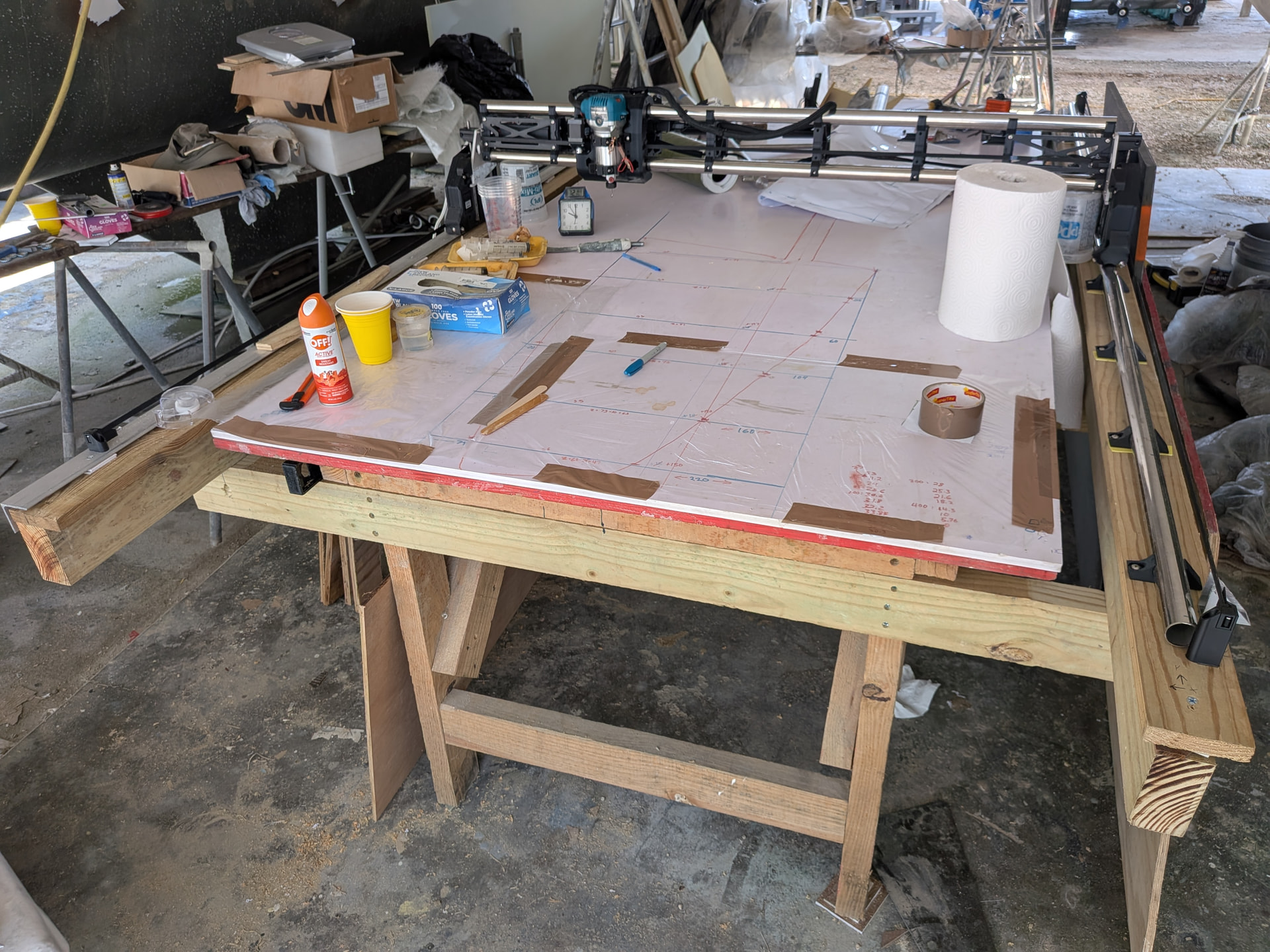
Here is a shot of the whole setup. I reused a table someone else gave me in the boat yard when they took off. So I had to adapt it a bit with adding the wings.
Also for the tube lengths I used the online calculator and used what it said for the 4x8 sheet size. I’ll measure them again to be sure but I was pretty careful about that. Now that I understand how it works, I’d probably go 1-2 inches longer on the X and at least that on the Y. But later, I might have less space so I could understand people wanting to keep it tight.
In the instructions, there is a link for a few tables in CAD, on from me, that gives pretty accurate numbers…but they do vary. The best thing to do is set the machine on the rail and check before you screw down your tabletop. That is actually how I do it.
Same thing here, the endstops go at the end of the rail, use the CAD or the actual machine to set the top sheet. Y=0 is where the endstops trigger, you should not be able to go y negative unless you use a large pulloff value. Y=max is not constrained so nothing to set there.
I know it seems odd that there are no exact dimensions given for a machine like this and the table but the table dictates where the endstops go, the endstops determine where the machine sits at zero, and the machine dictates the sheet placement. So if I told you where the sheet goes then you would have to work backwards and try to place the endstops and machine exactly, much harder to do. On less than a full sheet the location does not matter at all becuase the whole thing is covered.
Hope that clears it up, build the table with no spoil board, place everything, spoilboard last.
That makes sense. I realized afterwards I hadn’t thought about that part. We had a lot of work to do to get things relatively flat as the original table was a quick work table so the focus went to that. When I leave here, the machine and the tubing is coming with me and the next table will be more precise and I understand what you mean about how to go about positioning it. I’ll definitely do that.
One question – just be 100% clear I understand – the surface that the bearing wheel side runs on and the tube mounts are screwed to should be on the same plane as the top of the table before the spoil board? I tried to align to the spoil board. I was going to buy another 1/2" sheet of MDF for the spoil board but would it be better to go thicker to push the spoil surface up higher? My plan was to use a 1/4" router bit (16mm cutting) to surface the MDF as the table surface is fairly good but not perfect.
The frame of the table should all be one plane, the wood the tube clamps screw to should be the same as your spoilboard, then everything will be co planar.
Have a look at the CAD, that might help clear things up for you.
At the same time…it does not matter. The spoil board can be a bit lower or a bit higher. The table can be bowed or twisted and doing one surfacing run will true it to itself (for 95% of CNC work, this is perfect)
I don’t know if I understood correctly, but I had no issues with this, as I used the SVG generators for the torsion table in the forums. Those calculators basically give you all the table widths and lenghts. After that all you do is home the machine, set it to XY 0, then set it to it’s max X and Y lenghts so you can measure the diagonals for checking if it’s square and basically those are the furthest corners your cutting area consist of.
That’s good to know. I want to make a smaller table, if I can figure out where to store it on the boat, to have a maybe 4x2 cutting area. I’ll try the SVG generator for that.