one other thing I noticed was whenever I have the Micro usb in the skr proI get printer not connected on the is display is that normal?
Hi Guys ,
I am back at it again I change the drive to Tmc 2130 my question is do I bend any pins on the driver itself ?
This is results I get when I do and M122
SENDING:M122
		X	Y	Y2	Z	Z2
Enabled		false	false	false	false	false
Set current	900	900	900	900	900
RMS current	887	887	887	887	887
MAX current	1251	1251	1251	1251	1251
Run current	28/31	28/31	28/31	28/31	28/31
Hold current	22/31	22/31	22/31	22/31	22/31
CS actual	31/31	31/31	31/31	31/31	31/31
PWM scale	255	255	255	255	255
vsense		1=.18	1=.18	1=.18	1=.18	1=.18
stealthChop	true	true	true	true	true
msteps		0	0	0	0	0
interp		true	true	true	true	true
tstep		4294967295	4294967295	4294967295	4294967295	4294967295
PWM thresh.
[mm/s]
OT prewarn	true	true	true	true	true
triggered
 OTP		false	false	false	false	false
off time	15	15	15	15	15
blank time	54	54	54	54	54
hysteresis
 -end		12	12	12	12	12
 -start		8	8	8	8	8
Stallguard thrs	0	0	0	0	0
uStep count	65535	65535	65535	65535	65535
DRVSTATUS	X	Y	Y2	Z	Z2
sg_result	1023	1023	1023	1023	1023
stallguard	*	*	*	*	*
fsactive	*	*	*	*	*
stst
olb		*	*	*	*	*
ola		*	*	*	*	*
s2gb		*	*	*	*	*
s2ga		*	*	*	*	*
otpw		*	*	*	*	*
ot		*	*	*	*	*
Driver registers:
		X	0xFF:FF:FF:FF	 Bad response!
		Y	0xFF:FF:FF:FF	 Bad response!
		Y2	0xFF:FF:FF:FF	 Bad response!
		Z	0xFF:FF:FF:FF	 Bad response!
		Z2	0xFF:FF:FF:FF	 Bad response!
Testing X connection... Error: All HIGH
Testing Y connection... Error: All HIGH
Testing Y2 connection... Error: All HIGH
Testing Z connection... Error: All HIGH
Testing Z2 connection... Error: All HIGH
no stepper movement when I send out commands ![]()
This indicates there is no communication between the skr pro and any of the TMC drivers.
It does look like you are using dual endstop low rider firmware now though. Do you have a low rider or a primo?
The TMC2209 use UART to talk to the skr. The 2130 use SPI. The jumpers on the skr pro need to change to connect the spi instead of uart.
In he manual on pg 12/18, it shows which jumpers need to be installed for spi mode.
The MOTOR power input also needs to be connected:
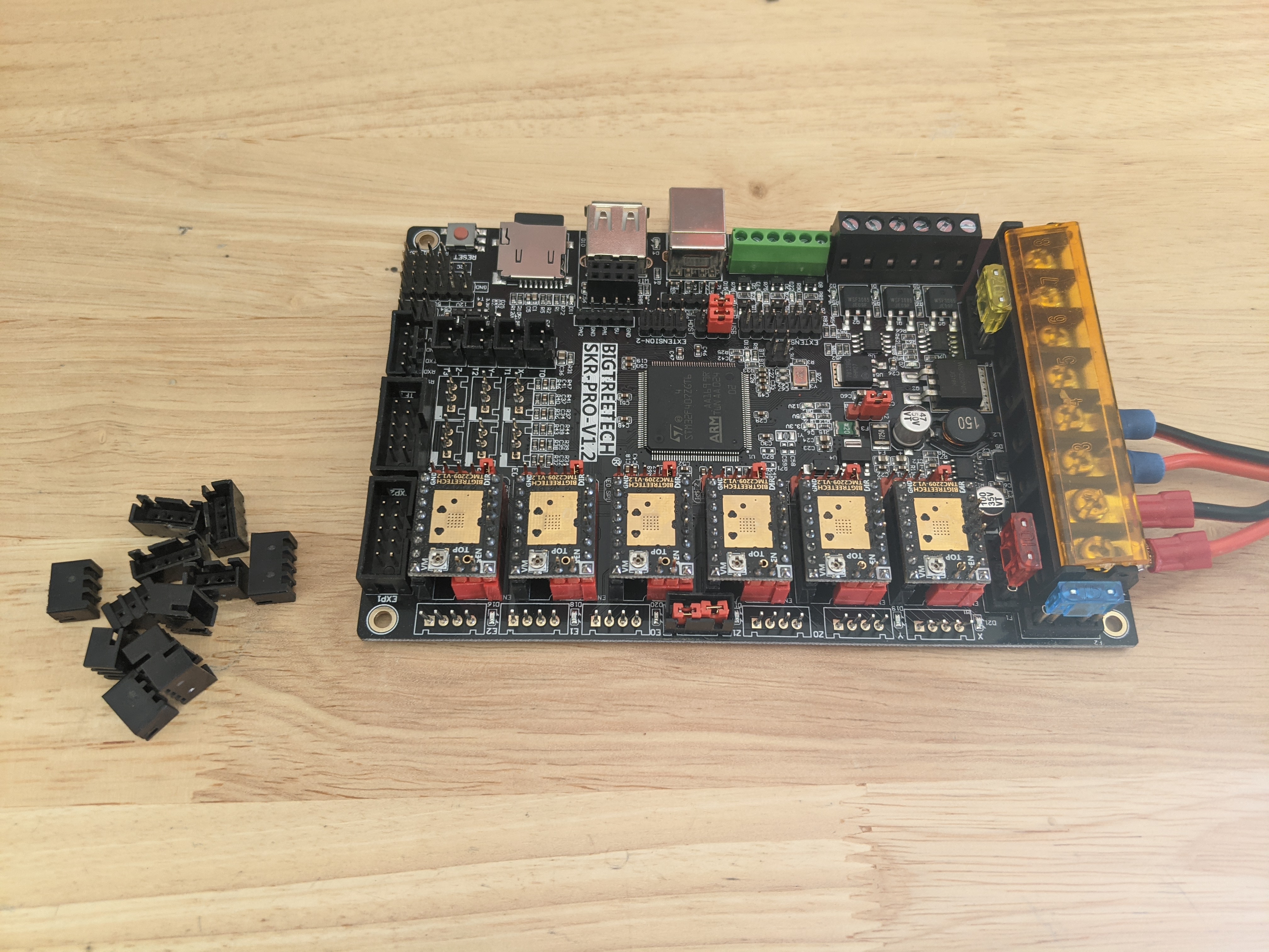
You can see how the 12V comes in to two places on the right.
The bent pin thing is to disconnect the sensorless homing pin. You don’t have to worry about that yet. The motors need to tall to the skr pro and actually move before you worry about endstops.
And just like that it works - you are the Greatest Of All Time ( GOAT) . I highly appreciate all the support and I am building a Low Rider V3 . Thanks
1 Like
SENDING:M122
		X	Y	Y2	Z	Z2
Enabled		true	true	true	true	true
Set current	900	900	900	900	900
RMS current	887	887	887	887	887
MAX current	1251	1251	1251	1251	1251
Run current	28/31	28/31	28/31	28/31	28/31
Hold current	22/31	22/31	22/31	22/31	22/31
CS actual	22/31	22/31	22/31	22/31	22/31
PWM scale	0	0	0	0	0
vsense		1=.18	1=.18	1=.18	1=.18	1=.18
stealthChop	false	false	false	false	false
msteps		16	16	16	16	16
interp		true	true	true	true	true
tstep		max	max	max	max	max
PWM thresh.
[mm/s]
OT prewarn	false	false	false	false	false
triggered
 OTP		false	false	false	false	false
off time	3	3	3	3	3
blank time	24	24	24	24	24
hysteresis
 -end		-1	-1	-1	-1	-1
 -start		1	1	1	1	1
Stallguard thrs	0	0	0	0	0
uStep count	376	328	712	8	8
DRVSTATUS	X	Y	Y2	Z	Z2
sg_result	76	77	80	82	75
stallguard	*	*	*	*	*
fsactive
stst
olb
ola
s2gb
s2ga
otpw
ot
Driver registers:
		X	0x81:16:00:48
		Y	0x81:16:00:44
		Y2	0x81:16:00:4E
		Z	0x81:16:00:4A
		Z2	0x81:16:00:49
Testing X connection... OK
Testing Y connection... OK
Testing Y2 connection... OK
Testing Z connection... OK
Testing Z2 connection... OK
1 Like
Guys what is the best bin file to add to my folder ?
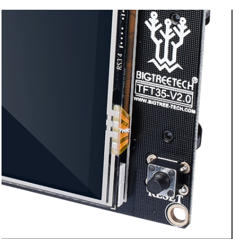
Add them all. The screen will choose the right one.
Can Some give me an idea where to connect Z endstop on my setup - I do not see one on this picture .
Do I need to make any modification to the firmware in order to use this set up . Thanks
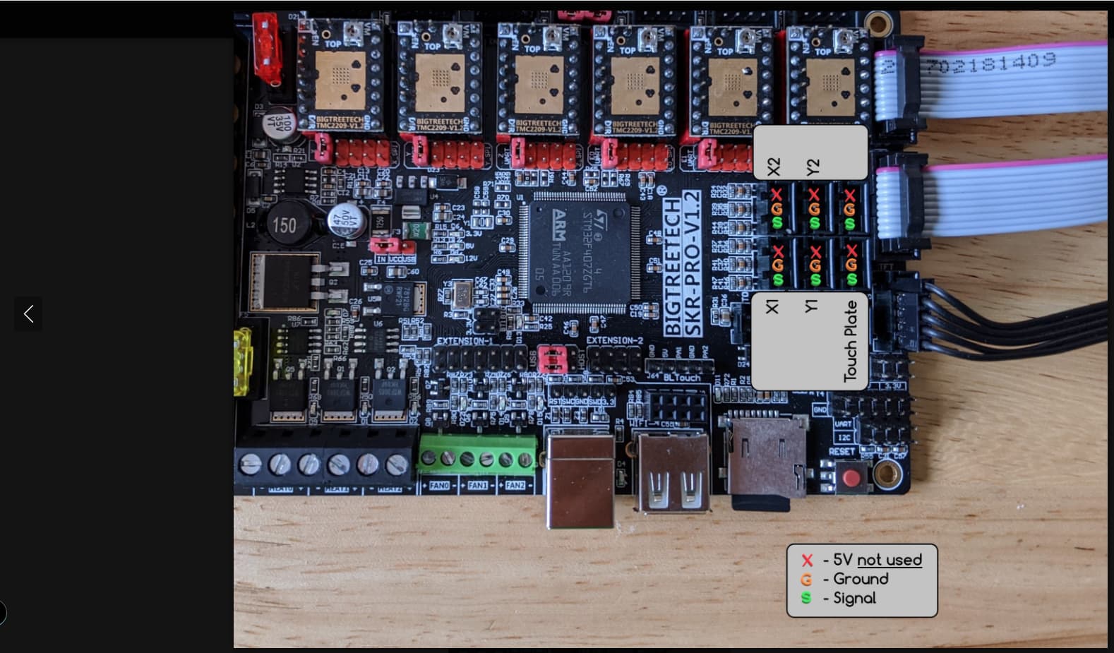
As-is, the firmware homes Z to the touch plate, and not to Z Max. (The unlabelled port in that picture.)
So yes, you will need to modify the firmware to home to Z max, similar to how the LR firmware does it. That also means that tou will need to define thr Z_Min stop as a probe pin, allowing the use of the G38.2 command to probe for Z=0.
I don’t have those edits handy right now.
Thanks for the heads up if someone can give me the edits - that will be awesome . Thanks