Bigtreetech octopus on Lowrider V3

I’m not seeing an option for dual drivers for rotary axes (I, J, or K), but I think you could do just as well by wiring the motors in series from a single driver. Both motors will get full current (full torque), and only the top speed will be somewhat less, but I doubt you would need several hundred RPM.

As for setting up 5160’s, I think it is enough to specify
#define I_DRIVER_TYPE TMC5160
Everything else should fall into place and it should use the proper CS pin. The X2 axis is automatically assigned to E0, Y2 is automatically assigned to E1, and I is automatically assigned to E2 (compiler will warn about automatic assignments).

Of course you have to make sure the jumpers and everything is configured correctly. For the Octopus board you don’t have to snip the DIAG pin (sensorless homing endstop signal) because there are jumpers elsewhere on the board to connect or disconnect the DIAG pins to the endstop pins.

Then you will also need to define
USE_IMIN_PLUG
INVERT_I_DIR
I_HOME_DIR
I_MIN_POS
I_MAX_POS

and a bunch of other fields will need 4 elements instead of 3, like
DEFAULT_AXIS_STEPS_PER_UNIT
DEFAULT_MAX_FEEDRATE
DEFAULT_MAX_ACCELERATION
NOZZLE_TO_PROBE_OFFSET
HOMING_FEEDRATE_MM_M

And then in Configuration_adv.h:
HOMING_BUMP_DIVISOR
AXIS_RELATIVE_MODES
MANUAL_FEEDRATE

Basically the compiler will give you errors on all of these, which seems scary because it looks like a lot of errors, but each one is simply something undefined for your new rotary axis. The compiler will tell you what you need to do.

I haven’t yet gotten to the point of setting up a true 4th axis (“true” meaning not just using Y as rotary) but I’ve been looking ahead at what it would entail on the Octopus and this is my best guess.

I need to clarify, I dont need dual axis on the rotary. I just don’t know if I am going to use the 4th axis parallel with the Y or the X axis yet, but only plan to use one driver and one stepper to drive it. I was just going to use the Pedros files modified by Antwan as it appears to already be set up for 4 axis and just modify them for my 2209’s, but I can not get it to compile, getting
Error: Unknown environment names ‘STM32F429ZG_btt’

1 Like

Ok, for that particular error, you’ll need to open platformio.ini and change this line (from Pedro’s version):
default_envs = STM32F429ZG_btt
to this:
default_envs = BIGTREE_OCTOPUS_V1

Then you will (probably) get some other errors that can inform what you’ll need to do next.

I have tired that and it does let it go to next error, which I think has to do with my folder structure of marlin, or how I am openind the project in VS code. I had this same error before and it was something do with my folders not being correct. Here is the error I am getting now;

Error: MOTHERBOARD is not defined in Configuration.h

What enclosures are people using for their Octopus based LR3 builds?

Also, thanks for the firmware and other info in this topic. Cheers!

1 Like

Anyone able to share pictures of their Octopus wired up? Ideally one that’s co-existing with a Raspberry Pi. But pictures of any Octopus builds would be appreciated.

Drilling holes in the existing SKR Pro case is the fastest way to get this done. But that’s too simple, straight forward and efficient. There’s got to be a more complex way…

Currently trying to decide on a layouts with minimum clearances, still planning to gantry mount.

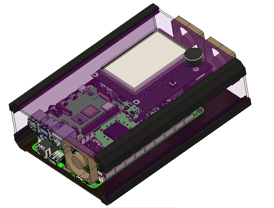
I still need to make room for 1) wiring to snake underneath the board, 2) wiring to go in/out either side of the case. Plan is to 3D print initial parts, wire up, then CNC the rest… Will then iterate and evolve to improve/Mod.

Incase you haven’t seen already, Ryan recently posted…

Cheers!

1 Like

So true.

Your cut-out box has been stuck in my head. It makes so much sense. Just make a minimal board mount, just enough so you can run the machine, and like the LR3 struts, ideally the same material you cut the rest of your board box…

Or redesign the beam so everything fits in it.

2 Likes

Yeah, there’s a lot of space within a stock LR3 gantry/beam. Without any gantry changes, the gap below the rear strut is already large enough to shove in the V1E power supplies and Raspberry Pi cases even. Any concerns about wood and alu dust/chips though for unsealed enclosures? Raspberry Pi’s overheat too easily imo, feels like tinder box in the making…

For headless… Cased SKR/Octopus could be shoved into the gantry as well if Rear Strut’s first section was removed—or, maybe, just notched at the bottom to allow enclosure to slide in. Vac hose would be raised slightly and end up resting on the enclosure. I have no idea if hacking the rear Strut like that would overly compromise the overall beam’s rigidity/performance. Maybe a slim air dust tight heat dissipating folded mostly sheet metal case (Home Depot HVAC metal stock thin enough to fold with CNC cut wood jigs…)?

For TFT users… Like myself, am happy mounting a box similar to stock LR3. Easier to inspect, maintain and clean the SKR/Octopus and ESP32/Pi if they’re air cooled, and further away from the router dust/chips.

Yes, my plan is to print minimal viable board mount, just enough to be able to wire up and operate LR3. Then, will get LR3 to hole, carve and contour the enclosure panels. Ideally, design in a way that allows case assembly around existing wired up board… Similar to how LR3 makes own Struts. Machines that make themselves brings me joy—until they turn on us.

Will share files if I get anywhere. Was originally hoping someone had already made a LR3 gantry mounted Octopus/Pi/TFT case, maybe squeezed in a display for the Pi even…

Edit: Lots of enclosure options out there for Octopus with/without Pi … Printables

2 Likes

Not sure if this would work, but…

Use an aluminum box for the pi. Use heatsink tape to mount pi to the box. Now the entire box is the heatsink for the pi.

2 Likes

When pis overheat, they slow down enough to not hurt anything. The smoke temp of wood is so much higher than the CPU would ever get.

My rule of thumb is, if you want max speed out of a pi4, you need at least a heatsink. A small fan would also work fine. The 3B+ worked fine without any help as long as it wasn’t in an enclosure. Octoprint works fine on a rpi4 without a heat sink in my experience.

I don’t think you could boil water with a pi. Let alone start a fire.

4 Likes

I knew I remembered seeing a Pi4 case that had no fan on it. This one uses the case as a massive heat sink

Edit:
Although, I think this is the one I was really thinking of:

2 Likes

Hey @jamiek / anyone, are you using buck convertor to power your Pi, if so which? Or are you happily powering your Pi off the Octopus board, maybe that’s ok for Pi 3+. But for Pi 4, am less confident.

From Jamie’s build topic Outdoor IDEX build - #69 by jamiek

Octopus User Guide says…

  • Max 5V 8A on page 7
  • Board has 5V headers (J26) specifically to Power Pi on page 10. Can see J26 Header/Pins, but searching for J26 on Schematic didn’t reveal max current for the header. Am assuming it’s good for what ever the board and J26 dupont pins are capable of (3amp).

Planning to run Pi 4 (acquired during the before times) which consumes ~3.0A, currently leaning towards decided to give the precious Pi it’s own buck convertor power supply isolated from whatever is going on with the Octopus connected steppers/fans/lights/etc… Also thinking probably better (decoupled fate/cycling) for the Pi to not be harshly reset as frequently as how often I need to reset/abort Octopus job.

Yes, I am using a buck converter for the Pi (far left in the picture above).

I had seen the 5V for the Raspberry Pi connection but it was after I had already hooked up the buck converter. It does make me curious. If it’s intended for the Pi, I would hope it could deliver enough current. It would be nice if it worked. It’s worth an experiment. I’m not sure if I have a suitable resistor, but maybe I can gang a bunch together, or maybe even a stepper can act briefly as a low-value resistor.

Or even just hook up the Pi and run a cpu-intensive program and see if the brown-out indicator trips.

1 Like

Thanks for the info and ideas Jamie.

Planning to keep Pi power separate, at least until my LR3 is working again.

Found an unused DROK Buck Converter 12v to 5v max 5A among my unused adapters. Uses synchronous high efficiency rectification, great, when it works… Wondering if they can fail latched sending full input voltage to destroy target device. Will test before using, but, might end up just using official Pi power supply if/when I find it.

I use a buck/boost converter on my pi. I have one on my printer too.

The header 5V pins are after any psu filtering circuitry on the pi itself. So a usb connection is better. In the last install, I soldered directly to the pads on the bottom of the USB power in port. That is my favorite way to do it. The gpio pins seem to leave me with a lot of warnings.

1 Like

I prefer to cut a cheap USB cable to power my pi.

1 Like

@niget2002, do you have an Octopus? Would love to see more examples of LR3’s powered by Octopus + Pi.

Feel like I’m reinventing the wheel here and someone’s already done this better already?

No. I’m running my pi attached to a MPCNC running a smaller controller.

1 Like

Anyone have Octopus based layouts/setups they’d like to share?

Currently wiring up, setting jumpers, firmware and such…

For TMC2209 Drivers looks like we set jumpers for UART mode. From 3.2 in Octopus User Guide.

For SKR Pro 1.2, for the PCB’s TFT connector, I removed the plastic female connector to help the Dupont cable make more secure connection. Anyone done the same for Octopus’s TFT connector?

EDIT: Ended up removing JST connector housings for steppers, endstops and tft. Yet to power up and figure out if I broke something…

1 Like

Boardkiller Aza. :sweat_smile: Wishing you luck.