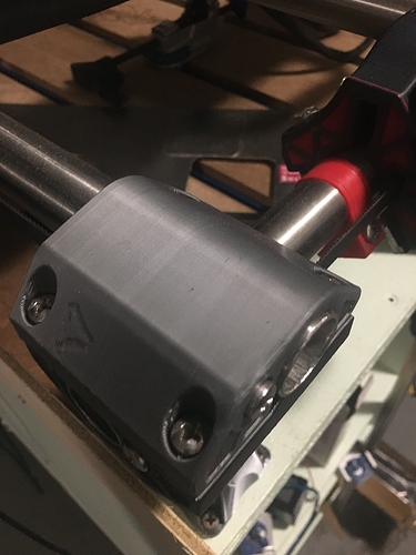
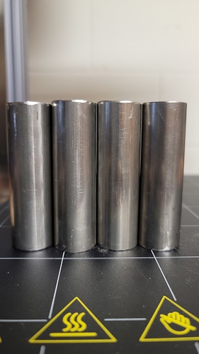
Here is a picture of one of my corners you can see that one of the tubes is sticking out more the the other…
That link doesn’t work, but I would love tonsee the jig. Been trying to figure out the best way to get them holes cut out
odd,
at prusa print search for " MPCNC Primo J 25.4mm Z-nut trap Jig"
try this one https://www.prusaprinters.org/prints/35297
Don’t see anything that looks like it would help drilling the holes… I seen one hight jig but that was it
Mark’s? Use the tube to fasten my drag chain to works well
I got my legs cleaned up, I’m planning on shimming the left one use a .8mm printed pla disk. Other than that i think they look to be pretty even and level.
If I get 5/16" bolts that are 1.75" long rather than 1.5 will that be a problem?
specificly i’m looking at getting these bolts and these nuts
I don’t think that will be an issue. You can change the direction they face in any cases where it might. Pretty easy to find the right size online though.
True but that is a package of 100 for under $2 not sure where else I would get that good of a deal… though not worth the 10 dollars I would save if it doesn’t work. Thats why I wanted to be sure 
Have you tested your creality board? I have one too but would need to add a stepper like you did. Trying to decide if I want to go that route or just buy the skr pro
I have not, I haven’t had a spare stepper around to test it with. But I just got a few in yesterday. So I will be testing it soon (hopefully in the next 2 days)
Sooo… tests of the board. I got the firmware working and all seems well… except the 5th stepper that I added. Its possible that I cooked the driver while soldering (its been a while since I have done smd soldering) not sure If there is a way to tell other than try putting another driver on the board and giving it a go.
Yeah. Swap the drivers and see what that does.
Also for those who care the cr-10s board v2.2 is apparently the same as a ramps 1.3/1.4 board XD
Another chip and another failure. Still couldn’t get the 5th stepper to work. Unfortunately that means I will probably end up buying a new board (im out of spare driver ics) though @ArstenA i encourage you to give it a go and would love to hear if you have any luck getting it working.
@Atom where have you been buying the stepper driver chips? I will need to get some. I will also have to try my hand at surface mounting a chip. I have done plenty of soldering but never tried surface mount.
How are you applying solder/solder paste? I will have to watch some YouTube videos. 
I have a syringe with solder paste that I use. As for the drivers I was pulling them off of an ender 3 board I had but I would imagine mouser has them for sale. I’m not sure if I cooked my chips or just haven’t gotten good solder joints. My eyes aren’t so good anymore and hands tend to shake a bit… makes applying that paste not so easy 
So do people have a recommendation on table hight, normally I go with 40" for these kind of applications but I’m open to other ideas.
Question:
the “clearance to remove Z axis” in the calculator, is that the amount of space needed above the total machine height? i.e. if the machine is 10" tall and the clearance is 23" then i need a minimum of 33" of height in my enclosure so that i can take the Z axis off?

