Any interest in writing software for the MPCNC?

Yes - I recently came across webassm and this small example when I installed the newer clang++ compiler on my linux box. I am really fascinated from this aproach because as far as I can judge you can create a native executable and with some modifications (mostly makefile stuff I guess) a web application.

As far as I understand the clang compiler is a frontend to the LLVM compiler infrastructure and generates some sort intermediate bytecode that then can be translated into different targets - webassemby (javascript…) being one of them.

Once I tried out an example and was astonished how well it behaved in the browser. Wish I had more time to dig deeper into it.

@rwillett
I really wish I had your background :yum: Especially when it comes to mathematics I deeply regret my lack of a higher formal education.

Where in a real world situation would it be necessary to cut multiple intersecting polygons?

You mean you had the user let decide which polygon has to be cut in what order?

I have to admit that the details of graphics programming is far over my head and I just dont have enough spare time to dig deeper into it, but when I can do some testing or something similar for you just let me know, ok?

1 Like

Most of the maths I use is from junior school.

Intersecting polygons are pretty common, imagine cutting a foam bed for a camera to slot into, the base of the camera is not a rectangle, it has cut outs for hand grips, the lens (or the lens barrel), these are all probably designed as different polygons with different depths.

The issue for me was that I was trying to do all of this automatically and sometimes it’s not obvious when there is an intersection which should be the ‘master’ polygon. Without an intersection it’s quite easy, though islands and holes complicate the issue.

The solution is to move it back up the stack to the UI and resolve issues there.

I wastrying to be too clever and got burnt.

Rob

1 Like

Finally had time to work on the software over the weekend and have managed to put a layer system in place for drawing objects. Whilst this may appear to be trivial, it took quite some time to get it right as the model for this in fabric.js isn’t obvious. I also took the oppotunity to rewrite a lot of the menu code so that as objects are moved back and forwards, the menus update to only display allowable options. i.e. if an object is at the front, then it can’t be moved forward anymore. This is important for work later on.

Now this is working, the next step is to write a bidirectional form interface allowing the user to enter information on the webpage that is attached to the object, e.g. height, width, rotation, bit size, bit direction, bit depth etc. This should (famous last words) be easier than before.

Once that is done, I can get back to the most important bit, generating the cut paths for all the objects. The problem before was I had to generate the objects the objects in the right order, the Z-Index and I simply got the basics wrong. Hopefully that is now corrected.

The moving things back and forth can be seen here.

2021-06-14 18-25-59.2021-06-14 18_27_28

Thanks

Rob

7 Likes

Finally managed to get bi directional forms working. In simple English, this means that I can set the height and width from a simple input field onto an object such as a rectangle, and as I change the rectangle using the mouse the height and width are automatically updated. This is needed to provide accuracy, as using the mouse is only so accurate.

It turns out its slighly more complex to write than I thought as propogating events in Angular and electron.js is a whole lot harder than Angular 1 and some hacks need to be put in place whilst I try and work out whether or not to put a simple message bus in which seems like a step waaay to far.

Anyway after spending two nights debugging a JavaScript method which turned out to be I was passing a string holding a number rather than a number <doh> basic JavaScript schoolboy error, I got it working.

The GIF below shows it working. I really need to learn CSS or SASS or anything to get the design right, but that’s a job for another year. This basically means I can enter numbers and get super accurate measurements which we need for a CNC machine. Big step forward as I now have a coding template for this :slight_smile:

2021-06-22 21-27-11.2021-06-22 21_36_36

4 Likes

Finally got to a point where things are taking shape, perhaps not a good shape, but better than before :slight_smile:

So we now have bidrectional forms, with zero validations, works. I can change the height and width, rotation etc. I can also set the CNC bit size, trivial at the moment. You can see the values change as I move things around. There is zero validation, checks or formatting.

Now we have a zindex, we can move objects backwards and forwards. This is the key change from my previous cockup. So an object on top of another object has priority over the underlying objects. Note the plural. So a shallow cut on the top object is more important than a deep cut of any of the objects behind it. To make this work, I need to automatically cut shapes out of the objects behind the higher object. Clearly the next highest object has priority over the underlying objects and so on and so on.

So here’s a longish demo that demonstrates that. I have different sized CNC bits with different colours to demonstrate the cuts that would be made. I still haven’t added in doing the edges or insetting the CNC bit in this version, I have the code. I wanted to check that the logic I now have works. The shapes are NOT updated for the cuts, that is the correct behaviour, I just need to see where the CNC bit would go, the rectange is still a rectange in the design, just that bits of it are not cut.

Hope this is clear.

Rob

V1_Update_12_07_21

6 Likes

And as I’d already written the code before, here’s the edge cutting lines. Nice when the code just works for once.

I offset the milling area by the radius of the cutting tool to allow the tool to go around the edge. This should produce a clean edge. I’m sure there’s loads of rules about directions of cut and number of flutes and speed but for the moment, this is enough for me. Get it working first and worry about optimising it later.

Screenshot from 2021-07-12 21-05-46

6 Likes

I’ve now the written the code to join the cut lines together. I had the code to cut the horizontal lines but no way to join the lines together. We also need to lift the CNC bit for some travel. paths, e.g. where we have a higher priority cut above it.

The green lines below show where a lift would be, the red lines show actual cuts You can seefrom the cross, that the left and right sections are their own cut and there is a green line indicating that the bit needs to lift.

I have removed the outside edge code so I can see what is happening.

The code to join the lines together will never be 100% optimal as it’s basically the Travelling Salesman problem. there are not enough resources in the universe once one goes beyond around 20 points. :slight_smile: This solution is based on Nearest Neighbour and uses a Kd-Tree to work out the clostest point.

Next step is to join the different blocks together. and that will use yet another Kd-Tree.

Once this is in place, work can start on converting cutlines and lift lines to gcode.

Joined up lines

I love the whole idea of what you are doing and would love to help out, but I suck at programming for computers, lol.
I read over your first post and noticed that this would be to generate g-code. Were you wanting it to be able to connect to an external control board to stream out the g-code, or just generate a file that something else would handle? Just curious what you were aiming for.
Keep up the great work!

@Cobalt

One (and the first) of the outputs will be gcode in a file.

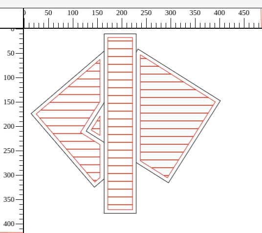
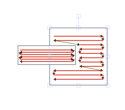
The lines generated in the diagrams above are an intermediate H/L representation. So I hold them as JSON structures. e.g.

[[{"p1":{"X":15,"Y":29},"p2":{"X":185,"Y":29},"cut":true},{"p1":{"X":185,"Y":29},"p2":{"X":185,"Y":44},"cut":true},
{"p1":{"X":185,"Y":44},"p2":{"X":15,"Y":44},"cut":true},{"p1":{"X":15,"Y":44},"p2":{"X":15,"Y":59},"cut":true},
{"p1":{"X":15,"Y":59},"p2":{"X":185,"Y":59},"cut":true},{"p1":{"X":185,"Y":59},"p2":{"X":185,"Y":74},"cut":true},
{"p1":{"X":185,"Y":74},"p2":{"X":15,"Y":74},"cut":true},{"p1":{"X":15,"Y":74},"p2":{"X":15,"Y":89},"cut":true},
{"p1":{"X":15,"Y":89},"p2":{"X":185,"Y":89},"cut":true},{"p1":{"X":185,"Y":89},"p2":{"X":185,"Y":104},"cut":true},
{"p1":{"X":185,"Y":104},"p2":{"X":15,"Y":104},"cut":true},{"p1":{"X":15,"Y":104},"p2":{"X":15,"Y":119},"cut":true},
{"p1":{"X":15,"Y":119},"p2":{"X":185,"Y":119},"cut":true},{"p1":{"X":185,"Y":119},"p2":{"X":185,"Y":134},"cut":true},
{"p1":{"X":185,"Y":134},"p2":{"X":15,"Y":134},"cut":true},{"p1":{"X":15,"Y":134},"p2":{"X":15,"Y":149},"cut":true},
{"p1":{"X":15,"Y":149},"p2":{"X":185,"Y":149},"cut":true},{"p1":{"X":185,"Y":149},"p2":{"X":185,"Y":164},"cut":true},
{"p1":{"X":185,"Y":164},"p2":{"X":15,"Y":164},"cut":true},{"p1":{"X":15,"Y":164},"p2":{"X":15,"Y":179},"cut":true},
{"p1":{"X":15,"Y":179},"p2":{"X":185,"Y":179},"cut":true}]]

There will be thousands of these lines, each with a tool applied to it, be it a 3mm tool or a 15mm tool. Some will be cuts and some will be travel movement with no cuts. Some will iterate around as a cut may be a number of loops to get the depth.

The next piece of code I write will be to take these high level instructions and generate gcode from them.

However there is nothing to say that it must be gcode, it could be another output form. Could be PostScript :slight_smile: However the only things I have that understand anything are a CNC machine and a 3d printer, so I’ll generate a file and test it on gcode simulators.

This model of intermediate forms is quite common, in some respects I think of the drawings as the code, my program as the compiler and the gcode output as the binary code.

My knowledge of gcode is zero at the moment, but I’ve looked at the gcode specs and can see what it does so am hoping that’s not a major fag. It can’t be any worse than assembler (or I hope not).

Now as this is a specific output, it shouldn’t be a problem to have a different ouptut. Famous last words.

Does this explain things?

Rob

1 Like

Yep, it sure does, lol.

I’m a low-level junkie, bitwise operations and assembly are my favorite. I do lots of embedded design, so I’m usually poking around on custom hardware and making firmware for it. I really respect all of the high-level programming like you are doing because its actually hard for me to wrap my head around.

@Cobalt

I think of this work as similar to a compiler, I have written a number for profit and pleasure.

The design element is the program or the instructions. We don’t have a LR or LL grammer, but we do have semantics and prioritisation.

The h/l intermediate format is the p-code or the library.

The gcode is the assembler.

The analogy works quite well as:

  1. The instructions to cut a pattern can be considered a subroutine.
  2. We could generate different outputs for different cutting machines.
  3. The gcode can be optimised to reduce the number of operations.

We should get exactly the same results each time we run the code.

I’m just thinking through the next steps to handle the loops necessary to cut the patterns and how to make code to turn the intermediate form into gcode so that it’s modular and somebody else could write a function to run over the intermediate form to produce a different but valid output.

Best wishes

Rob

Have you been researching gcode much? I’m actually working on a system to read gcode and convert it to movement patterns for the steppers on my MPCNC. I’ve skimmed through the commands, but haven’t jumped into any real code yet. I’m still trying to get a good grasp on what the “universal” language is, or rather what set of instructions would be highly functional. From what I understand, the Marlin variant is the most popular with MPCNC folk.
I’ve also come to discover that file formatting is slightly different from Windows to Linux, which took me a minute to figure out when files that I generated would open fine under Windows but Linux would spit out garbage.
The joys of multiple platforms…

I’ve not done much research but I have looked through a number of programmes and some reference sites.

It looks pretty straightforward as it’s higher level than assembler and lower level than C. The structure is normally an operator followed by some args.

Until I get into it, I won’t really know, but at this moment in time, I’m not that scared of it.

Ah the vagaries of Windows vs Unix file formats. Normally it’s the end of line indicators \r\n on Windows vs \n on Unix, there’s also sometimes the end of file indicator, but that might have been DOS.

I’m just working out the rest of the HL intermediate format, mainly to reduce the number of CNC bit changes and to optimise the tool paths. Once I have that done (or at least an initial version) I’ll then look at working on gcode generation. After that, I’ll write a quick curl routine to interface to Octoprint.

Once I have that, I can create rectangles (can’t save or import them), overlap them, move them, generate an intermediate format, generate gcode and send it to the cnc machine. Then the real work starts…

1 Like

Also, if you are looking to do pattern matching on the gcode, might be sort looking at Flex and or Perl.

Rob

I was planning on doing it on a microcontroller, so it’ll most likely be C. I’ve already put together a prototype. It’s completely custom, not Arduino. :grin:

Ok, using something like a pic18 or similar will make things more interesting. Every byte will count.

What CPU will you use?

My current design is running on a PIC32MZ. It’s currently clocked at 150Mhz, but can reach 200 if needed.
I had started out on a 44-pin, 16-bit dsPIC33, but shifted to my 64-pin PIC32 mainly because I needed more I/O’s. I have a couple dual-core dsPICs that I would love to try out, but I haven’t taken the time to learn their architecture.
There’s more to it, I’m finishing up the proof of concept design right now and plan on making a dedicated topic for it later on.

I’ve wanted to take a run at controller software before, but then I got to thinking about speed limits and accelerations and operation lookaheads, and decided that there were much smarter people then me already working that problem domain, and that I couldn’t offer anything new, and my tears wouldn’t help with any pertinent aspect of my life… So I just created a new world for Dwarf Fortress. :hammer_and_pick: :bearded_person: :mountain:

3 Likes

I think making a new Draft Fortress sounds brilliant :slight_smile:

I also agree that I let other clever people worry about speed limits, aceleration, deceleration and all that stuff. I’ll stick to the simple stuff.

Managed to get the code working on joining all the cut lines together. Also added arrows so I can see which direction the cut is. Adding the arrows turned out to be really useful as the nearest neighbour was not efficient, it is now (for some value of efficiency that I decline to state :slight_smile: ) It goes backwards and forwards quite happily and the number of lifts to move around is reasonably low. However there is no optimum solution this side of the natural heat death of the universe,.

image

Next steps are:

  1. Writing code to work out how unique a CNC bit actually is. This is needed for when somebody wants the same CNC bit to work at different speeds and different stepovers (for example). To minimise the number of CNC changes we need to know how unique a CNC bit actually is. Mostly done but nothing interesting to see.

  2. Once I have that, I then need to look at adding multiple and different types of cutting to a shape, e.g. a pocket, an interior outline, an exterior outline, a tab (need to give that some thought). Some sytems uses islands but I don’t need those immediatetly as my system has an inherent Z-ordering. However once you import an SVG, islands might be useful. Multiple operations on the same shape is a pain from a UI point of view and I might be reaching waaaaay beyond my limits of CSS and UI stuff.

  3. And then finally I can work out how to join the shapes up in the most efficient manner. This code is worked out mentally but not written down. It’s very similar to a syntactic tree in a compiler with lots of semantic hints in it.

That’s probably enough for the next two weeks.

Rob

3 Likes