I think the AC pumps don’t move much air, but depending on how tight the box is, who knows? I’m pretty sure they pull much more vacuum.
No idea how much air a vacuum needs for the cooling, either. There is going to be a fair amount of leakage in the vacuum table, I’d think. I have a small shop vac that doesn’t get used for much because I lost the hose (the end has to be shaped just right to miss the filter). If I ever start feeling particularly destructive maybe I’ll just stop up the inlet and run it till it smokes.
I’m thinking you really don’t need to move much air. Maybe take a piece of 3/4" stock, mill a series of grooves in the X direction, interconnected on the ends, then make a top with holes drilled over the grooves, then print an adaptor to connect to the vacuum source. It seems it would be such an easy hold down for work that isn’t cut all the way through.
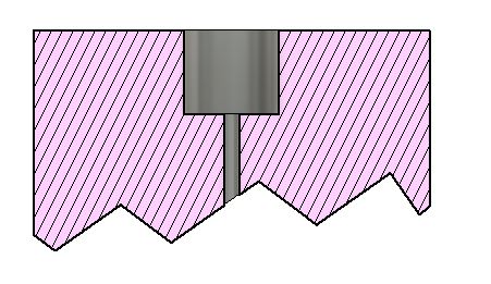
I researched vacuum tables awhile back and found an interesting design idea. When creating the hold down holes, a larger pocket is made next to the workpiece but a small hole connects that pocket to the shop vac. Here is a cutaway view of what I remember:
The claim was this design took some time for the vacuum to build up, but after the vacuum was established, the shop vac could be throttled back. In case where I got the idea, he had had an adjustment in one of the connections to let in some air to cool the motor. I’ve read in another place that a speed control was used after the vacuum was established to run the shop vac at lower speed (and avoid overheating). Also this idea might work for the vacuum pump you mention below with its lower volume of air throughput.
You might also consider a 2-stage arrangement where a shop-vac is used to establish the vacuum, and a vacuum pump maintains it once things have snugged down. If the shop-vac was connected through a check-valve, it could be turned off once the vacuum pump took over.
You want threaded inserts that have a flange and are screwed from the bottom. I’ve read of complaints of threaded inserts screwed from the top pulling out when used. I went with this style, though I’ve also read good things about t-nuts.
With threaded inserts, you might consider 3/4" MDF or even thicker. The common threaded inserts that I purchased were 13mm in length which would have stuck out in 1/2" MDF…and you also need to leave some space for surfacing the spoil board.
On my current spoil board, I placed my inserts 60mm apart so a single bag of 100 would evenly cover my spoil board. In my opinion 60mm is too far apart. If I did it again I would go a maximum of 50mm apart even if that resulted in incomplete coverage or I had to purchase another bag of inserts. And there are other pattern types for inserts beyond a rectangular grid.
For my next spoil board, I will use an even number of rows and columns so that the vertical and horizontal midlines are free of inserts.
Lately I’ve been happy using pegs and peg holes for my fences. Once the piece is aligned, I can pull the pegs out so I don’t have to worry about them during milling.
On my first spoil board I just used screws to either hold down the material or to hold down clamps. I made a lot of mistakes, some of which would have resulted in bits hitting inserts. So I’m glad I didn’t start out putting a lot of time into my first spoil board.
I’m going to disagree with the threaded inserts screwed in from the top. I’m using those and have yet to have any of them pull out. The forces on these machines are in the X and Y direction. Very little forces pulling up on the workpiece.
I also surfaced my spoilboard first, then drilled the holes and installed the threaded inserts. This guarantees that the threaded inserts are parallel to the x and y axis. If you drill the holes for the inserts, then flip the board over, you have to re-align the spoilboard to the machine.
Have you ever tried to hammer a T-nut into MDF? I’ve never had good luck with that. Maybe I’m the only one that’s had issues there, though.
I do agree that you want 3/4" MDF if using threaded inserts. Whether you decide to screw them in from the top or the bottom.
That was the thing that I never understood. If you have to flip the board, how do you ensure you’re perfectly aligned. Milling from the top ensures it’s perfectly aligned with the axes. I assumed there was a technique to get it aligned if you drill then flip, but I haven’t gotten that far on my “stuff to go learn” list.
Do you get any slop/movement from the pegs especially over time? Are you using simpler dowels or something more fancy?
My standard way of dealing with double-sided milling is to pick either a horizontal or vertical midline of the stock and author in two bore holes on that midline just the size of some specific dowels. These bore holes pass through the “stock” into the material below. The origin point for cutting is the center top of the stock. I flip the stock along the picked midline, and use the dowels/pegs to align the two sides for milling. In the case of the spoil board, you would bore through the spoil board into the backer board below for the pegs.
This doesn’t apply to the spoil board, but in general double-sided milling, when using the center top of the stock as the origin point, the origin point for both sides is the same. So if the steppers remain engaged and the router is returned to (0,0), the router is in the correct position to do the second side
If your spoil board fits tightly in a slot like I’ve see in many builds, this double-sided method might not work. The problem is that if there is any skew of the spoil board with respect to the MPCNC frame, your spoil board will not fit in the slot when flipped. So as an alternate, you can bore your holes from the top nearly through the material, flip the board, and then do oversized pockets (to account for any skew) for the flanges on the inserts.
Do you get any slop/movement from the pegs especially over time? Are you using simpler dowels or something more fancy?
I use simple 3/8 wood dowels/pegs. I cut dowel pegs first and test authored the bore holes in scrap MDF for a tight fit. I have only two horizontal and two vertical holes. The pegs don’t fit as tightly as when I first bored the holes, so there is wear over time. If I feel looseness has become and issue, I’ll just create four new holes. But the next time I have to bore new holes for pegs I’ll likely move to using 1/2 copper pipe for pegs (5/8" O.D.). The copper pipe will have less variation between stock pieces, and the larger diameter will be more resistant to looseness over time. Even moving to 1/2" or 5/8" wooden dowels would be an improvement.
I haven’t done this yet, but I have a plan to put the t nuts into the table I have below my spoilboard. I plan on putting them in from the top, then when I put the spoilboard on top I can use 1/2 or 3/4". I never have to worry about hitting the nuts. And I don’t have to worry about putting the nuts into every spoilboard. Each spoil board only needs hols drilled all the way through it witch can easily be done by placing it over the old worn out board and aligning it with the fence. Also if you use the right sized t nuts and holes. Because you have a full 1/2 or 3/4" of clearance you can use any clamp hole as a dowel hole :).
Just a thought.
Edit: oh and because the t nut flang is sandwiched between the table and the spoilboard I never have to worry about them pulling out the top or pushing out the bottom.
Matthias Wandel predrills tiny holes for the 4 pins. He pre drills everything. He gives them one tap to make the spots and then comes back with a tiny bit to make the 4 holes.
I used these at one makerspace. I loved the fact that after you pry up the finished work, you can easily get rid of residual plastic nails in the spoilboard by scraping them with a sharp scraper. I did feel like any sort of brad nailer (plastic or metal) is a very dangerous thing. My brother shot a nail into his abdomen once and didn’t even realize it until a day later, the wound was so small. Thankfully, no major damage once they cut him open to retrieve it. I note that plastic brads won’t show up on an X-ray!