To start, I just found the MPCNC for the first time last weekend and I immediately started printing parts!! I haven’t been this excited about a project in a long time!! I got into 3d printing and laser engraving a few years ago and now all I can think about is building a Primo, first for a CNC mill and then after that I want to build a larger format 3D printer. Here are my questions (please bear with me if my questions are off point or reflect a degree of understanding):
I’m not averse to buying a controller like the SKR Pro V1 but the DIY part of me wants to build it. I can find parts kits on AliExpress to build a Arduino/RAMPs controller with a display.
Are A4988 stepper drivers sufficient to operate the NEMA 17’s?
If I go this route, is it capable of running Marlin or GRBL? I think because my next project is going to be a bigger 3D printer maybe I should focus my studies on Marlin.
I currently use Lightburn with my diode laser. If I build a controller with the parts I mentioned earlier and use something like Universal GCode Sender, would this be a similar experience? i.e. Connect my laptop to the Arduino via a USB cable and send the GCODE that way. What if wanted to simply drop a the file on an SD card to take out the garage to use it? Is there a provision for that available?
In the build documentation on the on the calculator page there’s the statement “For a Primo MPCNC, 81mm is the shortest and I highly recommend that.”
Does that mean no more or no less?
81mm seems vertically limited if I wanted to build one as 3D printer?
I was thinking of going with 31.5" by 31.5" for XY. Too much for a first build?
Thank you for any guidance that you can provide to total noob.
Super thank you to V1 Engineering, I haven’t felt this giddy about a project in ages!!!
You can build it with ramps. The Rambos and the skr pro were chosen because they are easier to use and harder to break. The ramps and mega clones work, but they have really cheap parts in them. Ryan used to sell the ramps and he had to stop because so many were failing in his initial tests. But there are a lot of successful ramps builds. There is preconfigured firmware for ramps at MarlinBuilder releases. It expects drv8825s, but you can use it as is, or fix the two or so places where it matters. The steps per mm will be wrong, but that can be fixed with gcode.
That is the recommendation for a mill/router. The current advise is to not use the MPCNC as a printer. You can, but there is a lot of moving mass. Newer printers are cheaper and faster for the same build sizes.
It would work. But if you really want that size, the low rider 3 is going to work a lot better at that size.
You can connect Lightburn directly to a Marlin machine, or you can write the g-code to a file and deliver it using any g-code sender, or you can run the job from an SD card. Personally, with Lightburn, I save my jobs to an SD card since I don’t like having my laptop in the shop area.
For a Primo MPCNC, 81mm…
The issue is how far the tip of the router bit is below the core when cutting. Greater distances mean greater leverage and therefore more potential deflection. There are ways to have a tall machine while also mitigating the impact. You can 1) have a drop table that lowers/raises the working area, or 2) have multiple different heights of the spoil board that lifts shorter work towards the core, or 3) have adjustable legs. Personally, I occasionally do cosplay props for my daughter using 2" foam, so I made my machine with adjustable legs. My Primo spends most of its time with only 80mm of working height, but I can adjust the working height upward when cutting foam.
I was thinking of going with 31.5" by 31.5" for XY. Too much for a first build?
If your measurements are for working area (not machine size), then this size is on the bigish side for a Primo. There are Primos and Burlys this size and bigger, but you do pay a penalty. You might want to have an initial experience of a Primo of a somewhat smaller size…or consider a Lowrider.
Are A4988 stepper drivers sufficient to operate the NEMA 17’s?
A4988s will work fine, but, reiterating Jeff’s info, the V1 maintained firmware for the Ramps 1.4 board is configured for DRV8825 drivers. If you go with DRV8825 instead of the A4988 drivers, then you can use the V1 maintained firmware without changes (assuming the same display). You would not even need to compile the firmware. You can transfer the provided binary using XLoader.
running Marlin or GRBL…
Most V1/MPCNC machines run Marlin, though GRBL seems to be making some inroads. Typically, boards will be either Marlin or GRBL, though there are a few boards that will run both. You will get more support from the forum if you use Marlin.
Thanks so much for the great advice, I have a 5 pack 8825’s on the way!
Also, that “Software Workflow” article was really good for demystifying the process.
Lastly, I’m going to downsize the workspace to 710x710x81mm.
Well, you probably won’t hear from me again for a week or so, or at least until I get the rest of the pieces printed and the unit assembled. I started with the core, so the biggest piece is finished anyway.
I have ramps with 8825s. The only problem i have had is the lack of backfeed protection. I was in a hurry one day and manually moved the machine too fast. It caused a burnout on my board. But ramps boards are cheap and i already have a new one. just need to replace it.
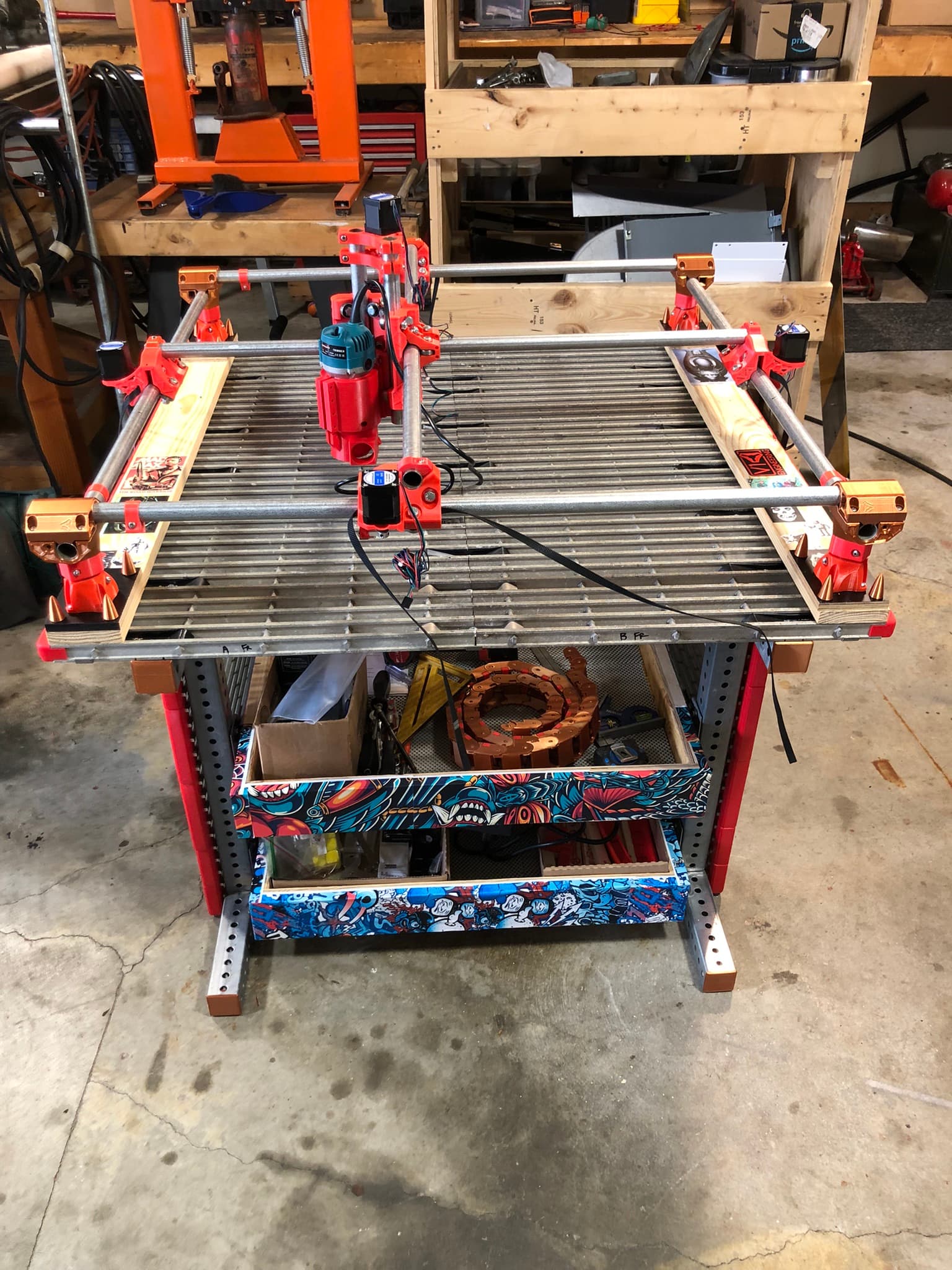
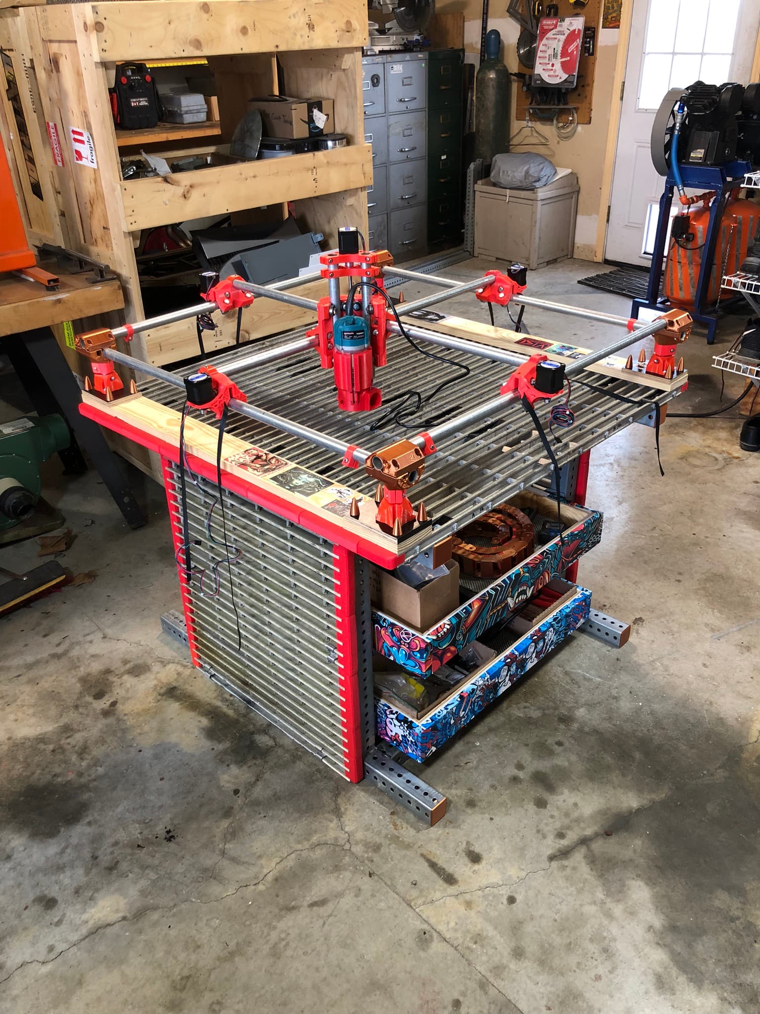
I now have all of my parts printed. I’m laying out my table now. I’m going to use those retractable casters on the legs. For the table base I’m going to use some aluminum catwalk grating that I have with 1.5" thick wood strips fastened from underneath the grating and then the corner bottoms attached to the wood. I figured then that I could quickly attach my spoil board in the same manner from underneath and change quickly when needed.
Couple more questions though:
I have a Dewalt 611 that I’ve used over the years for woodworking. Have any of you used a 611 on a Primo build? I did find a tool mount for it on Thingiverse. My gut says though that it’s too big around.
With a sharp endmill and moving slowly, will the 611 handle aluminum milling?
Not project related, how many MPCNC’s do you estimate have been built to this point? That’s just a curiosity question.
As always, thank you for all your help and knowledge!!
Just a quick update (as much for my own timeline as anything else)…
I got crazy busy at work so I haven’t had as much time to work on this project and I also picked up a new 3d printer which got me sidetracked.
I am almost finished with the table for the unit. As with most things I do, I slightly over-engineered the table in an effort to make it adaptable for other CNC projects down the road.
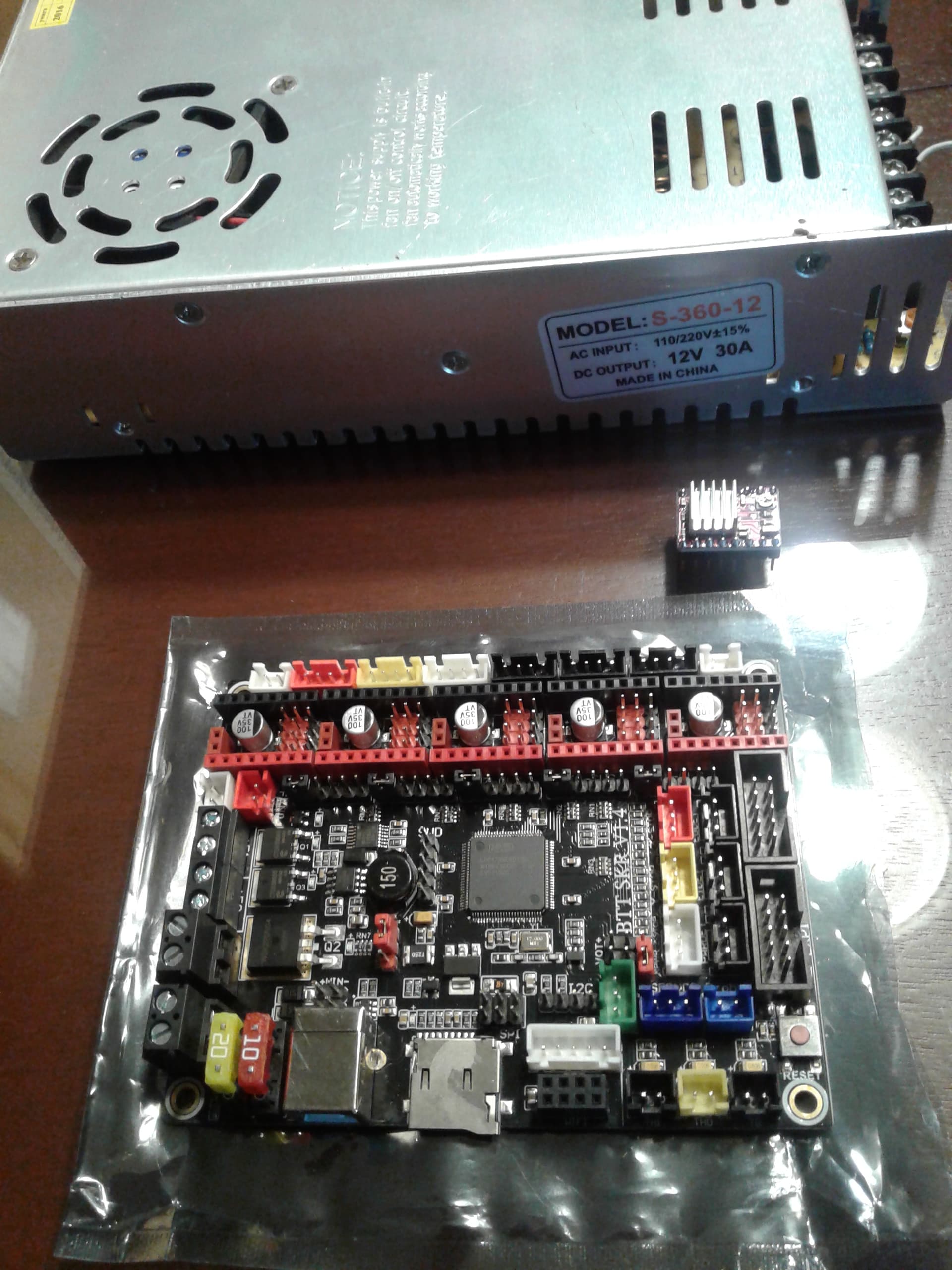
In the board setup instructions for SKR’s it shows how to place the pins to enable UART communication. The board in the picture is a SKR 1.2 and I bought a SKR 1.4 and there are some differences. Is my jumper placement in in the picture above correct?
On the 8825 drivers I purchased the chip sits on top. I guess I should still place the heatsink, just on the chip instead of on the copper base, right?
In the picture he had power on 1/2 and 3/4, what is the current on 3/4 used for?
The layout for the endstops input on the SKR 1.4 is different. 3 blacks, 1 white, 1 yellow and 1 red. Which gets which. I’m planning on using dual endstops as well as a touch plate.
I had an old power supply from another project hanging around (also shown in the background of the picture above). It’s way bigger than I need, 30 amp but I was hoping to use a DC spindle motor at some point down the road. Could I use this for both the control board and spindle? With a speed control for the spindle as well?
As always thank you for your help!! This community is the bomb!!!
Sorry, A few more questions, build related this time:
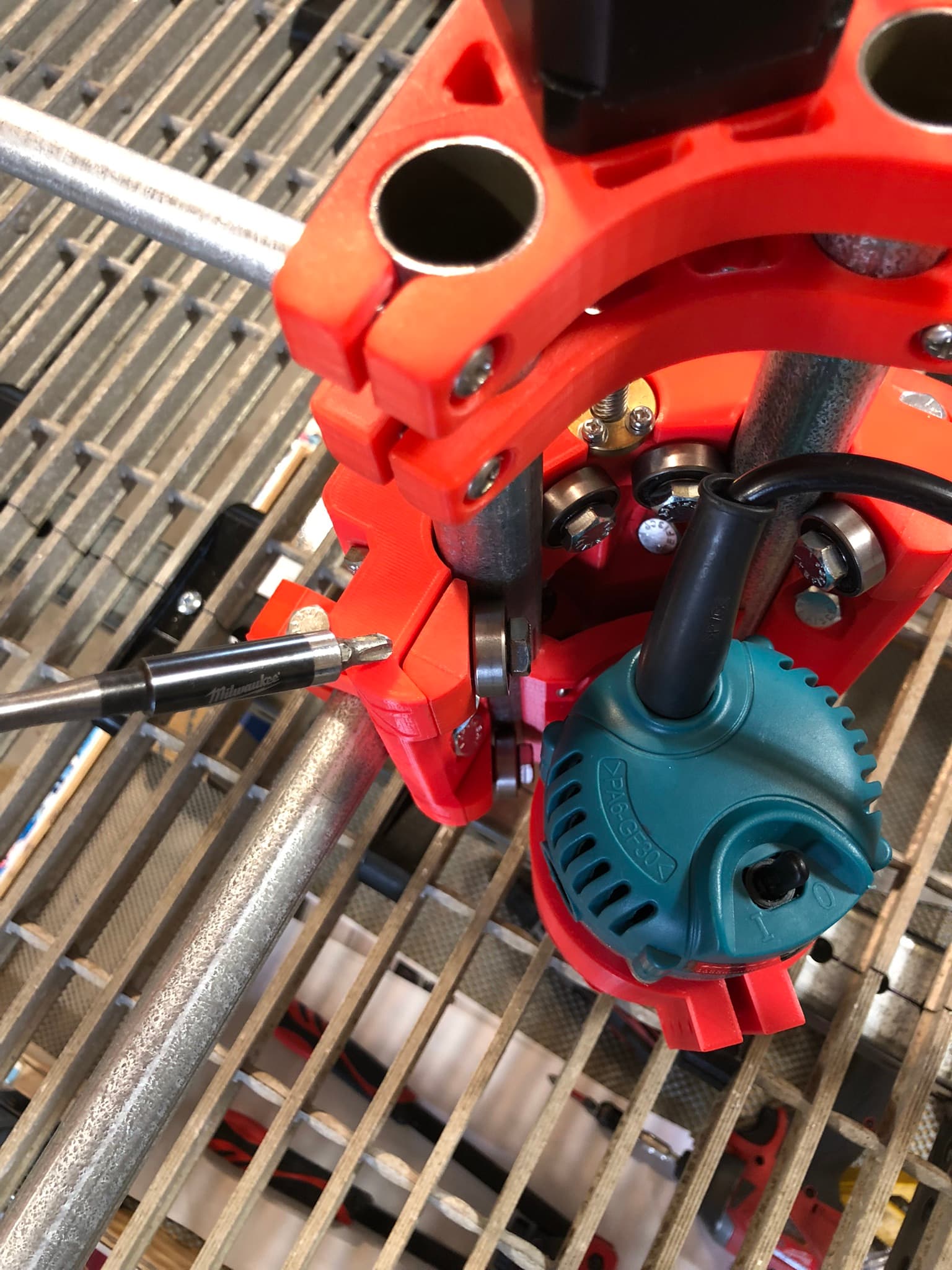
In the build instructions for the z-axis it says that when you put the last 4 bearings on the core that you are to barely tighten the bolts. It also says that you should be able to just turn the bearings with your fingers when they are in contact with the z-rails. I did this but the one CORE Z CLAMP isn’t back tight against the core as seen in the picture below, indicated by the screwdriver tip. When turned by hand my z axis moves really nicely with it as is. Is this a problem? (BTW I didn’t have the router in when I set it up)
They don’t have to. The more you fasten them, the more they “slide down” and get closer to the core. A lot of parts are clamping parts that should never touch. Your screws at the top where you attach the Z-Stepper to the rails also look very, very tight. You should loosen it or the parts will crack.
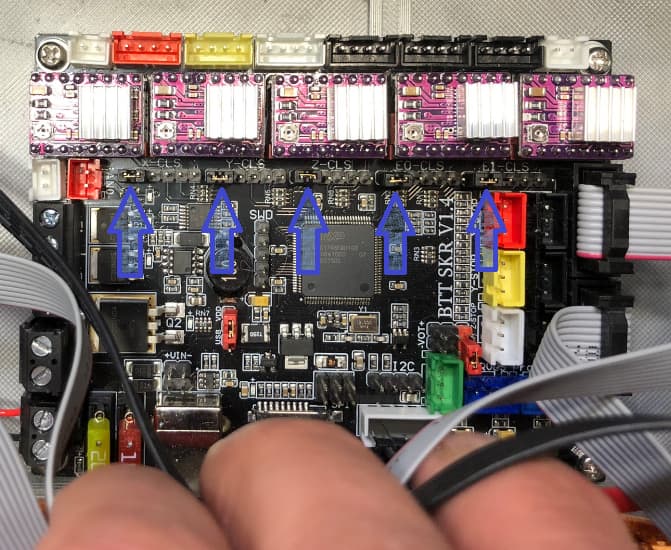
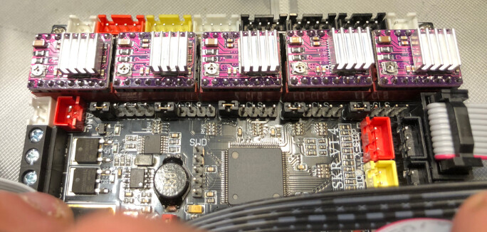
I was wondering if anyone had time to take a look at the controller that I’m working on. It’s a BTT SKR 1.4 (non turbo) with 8825’s. My 2 main questions are:
Is my orientation of the 8825’s correct? (BTW I have removed all jumpers from underneath the drivers.)
Do I have my jumpers set up properly for UART? On the 2 leftmost pins?
Do you think I’ll find a ready-to-go firmware for it on Github? I purchased 4 endstops from the V1 store and I have them installed. I just have to land them on the board yet.
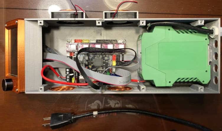
Here is my progress on the control box so far. I scavenged the Phoenix Contact 24v power supply out of a control panel we replaced at work. I get a kick out reusing things that would otherwise end up in dumpster!
BTW If you all think that it’ll be more work than it’s worth, I have a SKR Pro 1.2 with 2209 drivers. But it means I’d have to change my case layout and I was really happy the one I printed!
I took a look at some photos of this board with other drivers, and your enable pin is in the correct orientation, meaning your driver orientation is correct.
BTW I have removed all jumpers from underneath the drivers.
Most firmware versions that V1 maintains using the DRV8825 do not use UART and have all the jumpers installed under each driver. Current is set manually using the pot. Having all three jumpers in will set the board for 1/32 microstep resolution, which will match the default steps-per-mm in the configured firmware.
Do you think I’ll find a ready-to-go firmware for it on Github?
V1 maintains some versions of its configured firmware here. Previously a forum post on the SKR 1.4 suggested starting with V1 maintained firmware for the SKR 1.3 (V1CNC_Skr1p3_Dual_8825 for the dual endstop Primo). I don’t know if any changes needed to be made for the SKR 1.4. Perhaps Jeff (@jeffeb3) can give you some guidance.
I have a SKR Pro 1.2 with 2209 drivers.
This is the path of least resistance. This is a board and driver combination sold by V1, so there is tested firmware along with setup instructions for the drivers. With that said, I have seen SKR 1.3 and SKR 1.4 builds on this forum, so it can be done.
I’m going to go for it with the SKR 1.4 and 8825’s. If I end up tearing my hair out, I’ll switch directions and go with the SKR Pro 1.2 and 2209’s.
Another quick question, will the firmware for the TFT35 V3 E3 work for a TFT 35 V3?
As soon as I get this machine up and running (and I learn CAM a little better) I’m going to start building a full sheet LR3. I had a nice big area in one of my shops open up!
Thanks for all your help Robert! I’m anxious to gain more experience so that I can come on the forums and help others.
will the firmware for the TFT35 V3 E3 work for a TFT 35 V3
I don’t have an answer for you. Sometimes questions asked at the end of older, long threads don’t get answered. If someone doesn’t come along and answer this question, I’d suggest opening a new Topic on the forum with this question.
Based on reading on the forum, I know a couple of things. The ZIP file with the TFT firmware contains multiple versions. I think you can unzip the set to an SD card, and the TFT will pick the right version (if one is available). Also, the TFT firmware has not be configured in any way for V1 machines. The display will be set up for a 3D printer. To me, this implies that any firmware you find for that display will likely work.