3 Tube Gantry LR3 Build: An Idiots Tale

Now this is something I can really get behind! Looking forward to your results!

2 Likes

So both sides are just like this. My Z lead screws tilt in. They spin fine but don’t like the angle. I don’t think my YZ or XZ plates are warped (I checked them on my surface plate and they were relatively flat), and the alignment of my other parts doesn’t seem to be an issue. Idk if the Z stubs are a little shorter than they need to be or if my linear rails are somehow thicker than they should be. I may either modify the stubs a bit and reprint or make a ~1mm spacer. Could be that I’m just getting too much squish on the first couple layers of my printer as I do have a bit of elephants foot, but if I try to lighten up on the initial layer I don’t get as good of build plate adhesion.

Not sure it really even matters since the couplers take up the angle pretty easily, but it’s going to bug me being a bit canted over like that.

edit: Added 2 layers of card stock to shim the stubs 1mm and now my leadscrews are parallel to the side plates!

4 Likes

A couple of us building the Repeat printer noted a minor alignment change, too. I think that there may be more than one standard for the MGN12H rails, or rather the bearing blocks. The ones you have might be a little different than the ones that Ryan has and designed for.

The card stock shims should be good though. If it bugs you, you could probably re-print the stubs with a couple extra layers.

Something similar happened to someone else, it turned out to be an error in the 3D printer where it printed the Z drives to a slightly different scale in the Z axis than it did the stubs (Or maybe it was the whole XZ plate.) A reprint fixed that one,

2 Likes

I used some MGN12H rails I had from a couple years ago to a 3d printer I was going to build but didn’t end up using them so I suspected they may be slightly different. Just measured them from the mounting face of the sliding block to the back of the rail and they’re like 13.02mm. Looked at the specs of the rails on amazon from the LR3 link Ryan listed and they’re spec’d at 13mm in that dimension so I suppose it’s not my rails. May need to print a calibration cube on my printer to see if my z is off. Took 2 sheets of card stock which is ~ 1.1mm total (was going to use paper but didn’t want to have to cut out like 24 shims) and the alignment seems pretty close. May actually be out instead of in now by a tiny bit, but it seems acceptable. At least with shims I can always adjust them a bit if things move around (side plates warp, prints deform, etc).

It did give me a good opportunity to admire that all the critical dimensions on the gantry sides key off of the mdf\plywood (I used plywood because I had it on hand and they appeared flat on my surface plate, may recut them in mdf on the CNC once I get it up and running). Should mean any dimensional variances and thickness differences don’t really matter as long as the inside face is flat.

2 Likes

Closing in on finishing my gantry. Only 10" of Y travel (has to be some sort of record as this is almost too small to effectively do anything), but this config is just so I can get everything setup and wired in my office (it was 110f out earlier this week so I’m a little less inclined to work out in the shop). Once I get it built, I’ll be starting on a 4’ table. Used some 3/4" conduit for my temporary Y axis and some leftover 6mm belt from my birly mpcnc so I don’t waste my new 10mm belt. Need to swing by the hardware store to get some 1/2" conduit.

I really dig this silver silk PLA, has a very aluminum looking finish. Hard to capture with the camera, but it looks cool contrasted with matte black. Modified the screen bracket so I can attach it to the side of the controller enclosure to point more at me. This also aligns the cabling from the screen better so I don’t have to have it wrapping around the side and in.

I had my old MPCNC wired up with ethernet cable and it looks like it’ll be easy to reuse that, just have to shorten and solder on new ends.

5 Likes

So I’m finishing up my table this week, got a couple joints of 1/2" emt for my Y axis. I disassembled my gantry to fix a couple things and I got a weird idea. I’ve got a couple drops from my 1/2" emt that were longer than my X axis tubes. I don’t know if anyone has attempted to glue tubing inside of other tubing.

I whipped up a couple things in Fusion.

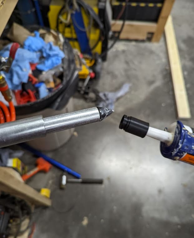
An adapter that will let me pump contraction adhesive into the 3/4" tubing. The bullet thing goes on the 1/2 tubing so I can push it through the adhesive. The rings I printed 4 of, they cap off both ends in the space between the 2 tubes. I cut the inner tube like 1mm shorter so it wouldn’t stick out.

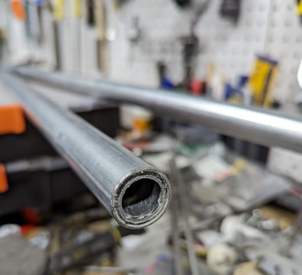
So I swabbed the 3/4" tubing with alcohol and paper towel, wiped down the 1/2" tubing. Filled quite a bit of adhesive, from my calculations with 32" tubing, the volume difference between the ID of the 3/4" tubing and the OD of the 1/2" tubing is about 11fl/oz. I used construction adhesive but epoxy or pva would probably be a better idea. It may take a long time for this stuff to fully cure.

Not sure if this will do anything but add more weight, but I can definitely tell it dampens the ring to the tubing.

3 Likes

Also, had to hide the sins of my horrible epoxy connector job (a relic from when this stepper was on my MPCNC)

3 Likes

It’s always fun to experiment and develop new techniques but when you factor in the additional weight you probably don’t gain too much. Did you run the numbers through a beam deflection calculator? You can approximate the new wall thickness as the difference between the ¾" od and the ½" id. That would be absolute best case. I suspect as the adhesive cures, the dampening characteristic you’re observing will change as the structure reaches maximum rigidity.

3 Likes

It appears best case scenario this decreases deflection by about half. Being there are braces every 7" idk if it’s fair to use 32" as a length in the calculation.

image

I also suspect that the damping of the adhesive may be moot regardless with the plastic braces and I may regret the additional weight if the z slips more when the steppers are disabled. I also don’t know if more gantry weight (within reason, as long as my steppers don’t lose steps) helps counter vertical forces. If I have any issues it’s another cheap fix to go back to stock tubing.

1 Like

Last night I did a couple things. The TFT35 screen I have is a 3.0.1 and the version of the tft firmware that works best for me doesn’t have much in the way of CNC specific stuff like zeroing the origin. I added some custom commands in the config.

image

I also finally installed my EP01S wifi module, which while my flasher should have made this easy, I was running into issues (I think because my module has a 32mbit flash size which means I needed to specify the location in memory to write the firmware. Idk).

It’s definitely no octoprint, but all I want it for is to be able to jog things around and so I can have an easy to get to list of macros that may be more complex than I can fit in the custom menu on the TFT. Mostly for setting origins, z probing, maybe a surfacing script.

I got a V1 touch plate in last week, I’ll have to think about what gcode to use for that. I plan on making a magnetic connector that I can stick onto my core, probe, and yank off once z probing is complete.

I also plan on adding an articulating air blast nozzle. It’s a tight squeeze with the shoe, but I think I can make it work. I modified the shoe to tighten up where they connect but they’re still a bit loose, may add a couple magnets so it snaps more into place at the core, could also add a bump out for the nozzle to fit in there a little better.

2 Likes

Yes, bracing 2 of these a few inches apart to create an I beam will dominate the structure rigidity. Doubling the rigidity of the tubes is likely neither here nor there in comparison.

1 Like

Yeah, if it does anything (questionable), would probably make more sense on a MPCNC

2 Likes

Any opinions on running the Y belt like this? Still working on how it’d mount and how to do limit switches. My thought was it’d mean the table could be a couple inches narrower and on the side using wheels (though not totally applicable to me since I’m attempting to use 2 Y rails) you wouldn’t have a belt sticking up that could be a bit more vulnerable in a shop to getting hit. Idk if there are pros\cons to running the belt perpendicular to the table vs flat. Also would be a smaller pocket for the Y steppers in the YZ plates.

1 Like

I do not think it will cause an issue other than you still need a gap, at the beginning and end of the belt, or the belt will be stretched and pulled upwards. And considering this, your savings might be limited compared to the original design.

Not sure how that is going to save any room but running the belt that way will gunk it and the pulley and idlers up. Sideways is far better.

At best you save like 3mm per side?

Fascinating topic, am also curious how 3x EMT, plus Struts, plus @claytonisbob’s other mods help resist lateral Y axis forces (more than a stock LR3’s puny 2 EMT gantry :slight_smile: ). Curious what feed rates you up maxing out at.

Oddly during testing we found that the rails only really help with torsion. Deflection is pretty solid with only the plates.

2 Likes

For a bit of perspective on Ryan’s comment there, the initial beta design called for 1/2" EMT for the X rails, and deflection was still pretty good. What we found there though is that near the center of the span, the gantry could twist, causing inaccuracy along the Y axis.

Because I had the steel from my LR2, I used the 1" X rails from the LR2, and that made it resist that torque.

3 Likes

Yeah I could really twist it, but deflection is super minimal. The only way I can think to help twist is add wires inside and that is not elegant.

3 Likes

Finally got some time to get back to the shop. Finished my table last weekend, should be able to cut my strut plates this week.

Just to show how uneven my floor is, even the leveling feet weren’t enough.

I’ll be adding some plywood to the sides and back to stiffen the table up later, but wanted to get going.

6 Likes