Used 16bit mode on µCNC to be able to at least keep up with Grbl execution speed.
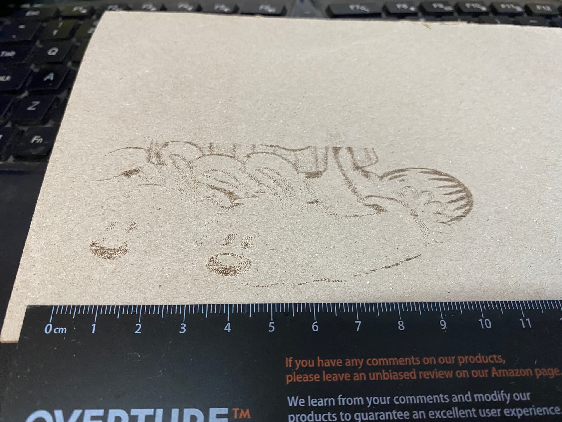
Besides the obvious engraving differences Grbl seems to underburn on the exterior edges.
µCNC has the opposite problem. There are obvious overburns on the exterior edges.
My first suspicion was that Grbl was using a lower PWM frequency then µCNC and the laser power was not updating fast enough. But they are using the same ~1khz pwm. But I don’t know. It may improve Grbl performance. Testing needed.
In the mist of all this I found a couple of minor planner optimizations that I will add to µCNC and I also want to add play around with laser pwm frequency to see if it adds any quality gain to engraving. I’ll also try to look at the overburning on the exterior edges thingy.
I’ll try to figure it out. I’m most probably doing something stupid (or multiple things) .
On µCNC the laser scaling is linear to the acceleration/deacceleration.
One thing is that the power is being scaled relative to the top speed of the segment and not the programmed feed (I’m not sure how Grbl does it) . That would explain the exit/entry overburns. This affects the density of energy the laser is sending to the surface.
This accidental bug seems to allow engraving at higher speeds but probably will also play with the contrasts. With higher overscan values might smooth the overburn.
If the gcode asks for 10mm/s and 25% power, then that segment should be scaling the 25% based on what fraction of 10mm/s it is currently moving (which would only be reduced by acceleration). If it was traveling at 5mm/s, the power should be 12.5%. That makes sense to me. That is what I would expect. But I guess it is sort of a contract between the CAM and the firmware.
I’m 100% with you on that. It is what makes sense. That’s a reason why this puzzles me.
I guess the thing is that at lower (standard engraving speeds) this is almost unnoticeable because the machine has room to reach the programmed speed and apply the correct power by mm/s.
edit: Just fixed tested the code that uses the programmed speed as reference and the results are now similar to Grbl. Overburn is gone and no noticeable underburn on the entry/exit. A bit more burning but not much better.
Unfortunately, a different laser may be needed to see any difference. A laser that is cycling on/off with the pwm frequency. Then maybe you could see some dithering.
I was hopping to see some improvement. Imagine you have really fast and short segments at different power levels. If you have a really slow pwm you might be executing two or more power level changes in a single pwm period. That would make the laser less responsive.
In this case it would be the feedrate of the G1 motion command and not the maximum feedrate that is achivable by that segment.
Edit: There is a discussion running around since late April about developing a new raster protocol that was raised by the laserGrbl developer. The objective is to try to overcome the GCode protocol inefficiency.
Lots of clever minds in this forum so feel free to step in and contribute.
Following on the footsteps of TerjeIO for grblHAL I’ve just added the needed modifications to µCNC on a new branch and a new module to support Smoothieware’s S clustering feature that is available in Lightburn.
I count on testing this feature this week and see performance wise, what this might bring to the table.
S clustering is a way of packing up to 8 different pwm levels in a single S command that is executed along a given relative distance.
I’ve also been working on PPI support has a core feature of µCNC. Although this is mostly used on CO2 lasers I’m very curious on how this can be applied to laser engraving.
PPI mode works like a sewing machine. It sets how many laser pulses (with a configurable fixed width) are executed per inch. The idea is that this will (I hope) work like dithering effect with the added bonus that is coupled to the motion and intrinsically to the motion acceleration. I’ll post the test results on that.
That is an interesting idea. Interesting challenges too. Trying to make sure you have enough resolution in that number that you don’t get major quantization errors.
How does the translation of PPI to duty cycle work? Do you have a set number of pulses max per inch? So if you had 1M max pulses per inch, and the gcode line set it to 500,000, you would compute the number of pulses in the next N milliseconds and pulse that many times, with half of them being off?
That doesn’t sound quite right. I need to write this down, or drink another cup of coffee.
The idea is this. You set 2 values. PPI (how many pulses per inch) and how long the pulse is (I guess the best translation for this is the power or laser exposure time). Don’t think of it as a duty cycle like PWM but as a beat. If your PPI is higher than your step rate then your laser will fire twice or more in the same spot.
If not it fires at a synched rate according to the position where it is (it does not care about acceleration because it is itself like a stepper.
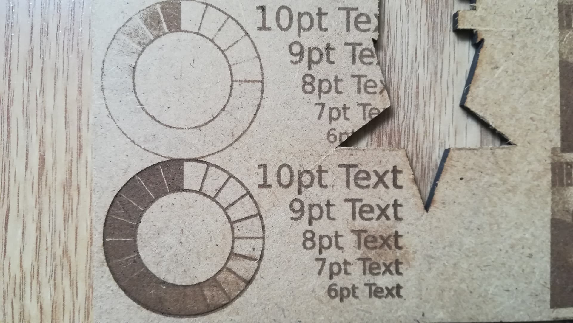
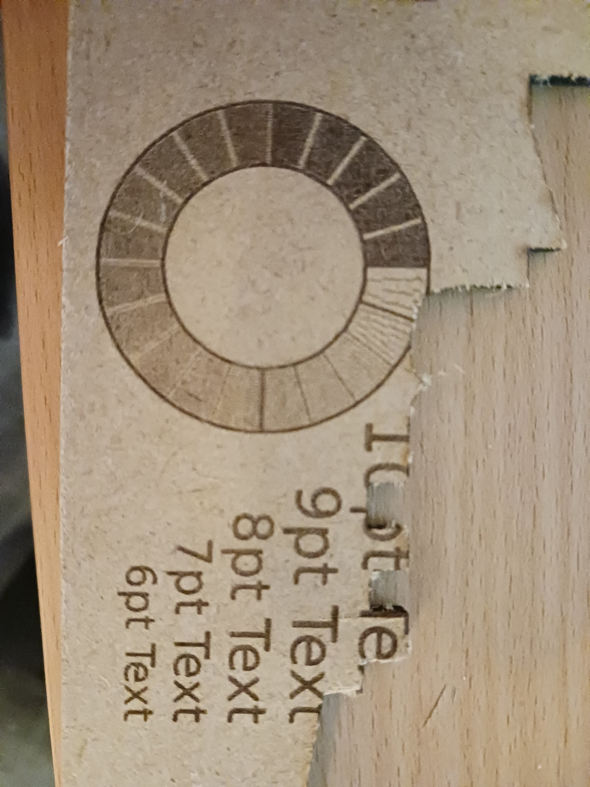
It took about the same time. This is 600PPI with an exposure time of 800µs.
You can see clearly “firmware” dithering in the clearer spots. it produced a few lines to give the shadow effect.
And just one side note. There is alot more to explore with this working feature.
Currently the S code works by changing percentage of the PPI value that defined. Lets say I set PPI to 600. S0 is 0% and S1000 is 100% of that value.
I wonder if instead of scaling PPI the S value changes the exposure time? Will it get even better grayscale and smooth the dithering? Or will work a bit like PWM?
And what if S changes both ?
I still have a ton of experiments to do on this one.
That’s really interesting. I get that it works now. The lines in the low power parts make me a little worried that it will be harder to tune. But there is a lot of ways to fix that. Very interesting.
It might be interesting to take some values and just determine the pwm frequency and duty cycle to see if they end up in a sensible range. In that clear section though, it seems like it is more like a bang bang controller. Nothing nothing nothing, bang.
It reminds me of the Bresenham 2D ray tracing algortihms. You step in one direction (X) and compute the Y by just adding the slope. If the slope goes over the cell size, then you add another cell to Y and subtract the whole cell size from your counter, keeping only the remainder.
That is exactly that.The laser pulse is treated as an additional axis stepper. The bresenham algorithm is at the core of the step pulse generator. All firmwares (except klipper maybe) use bresenham.
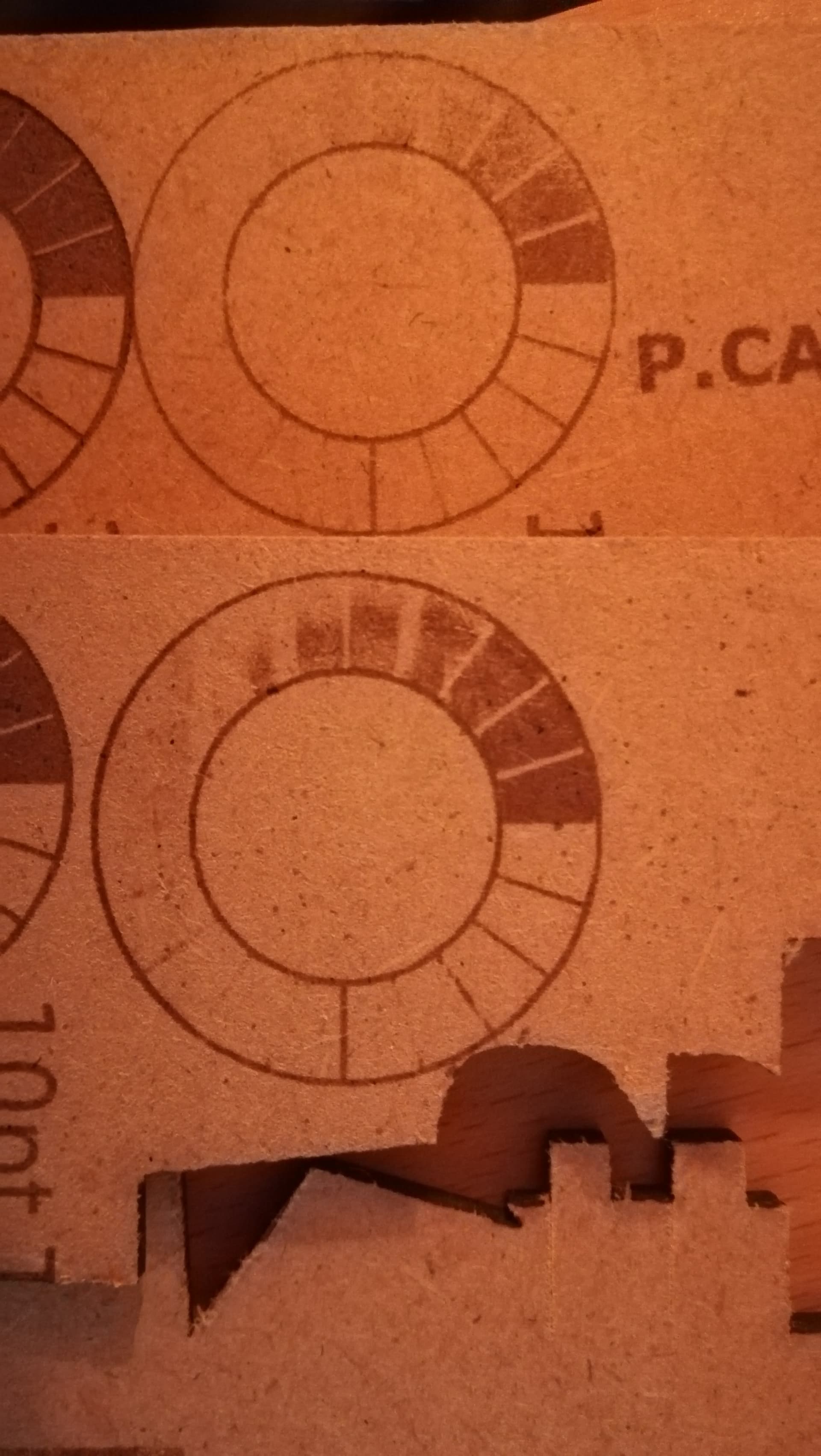
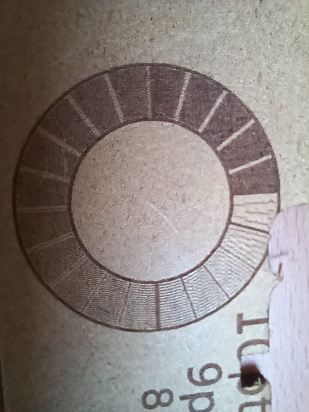
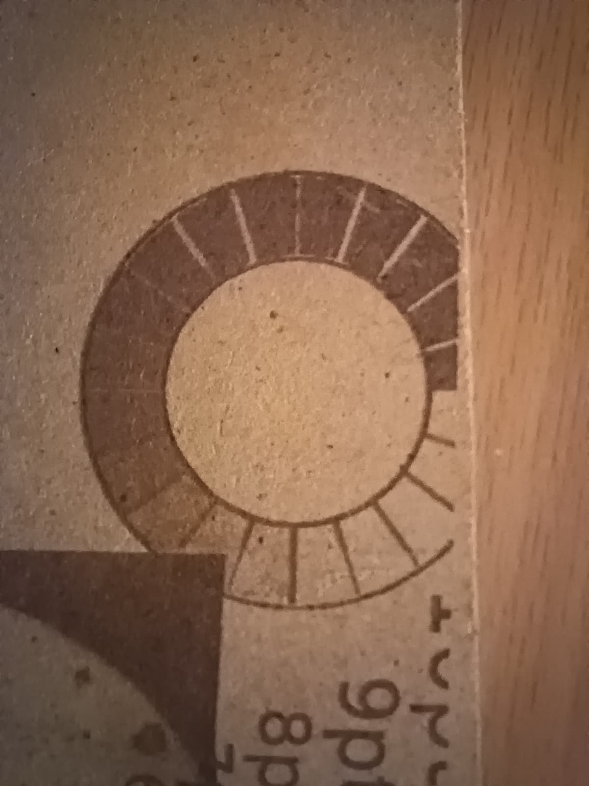
EDIT: Here is a closer photo with daylight.
You can see the efect created by the organized dithering. Since it’s not scatered or random it’s more noticeable.
I believe I’ve managed to implement the other flavor of PPI control were the S word controls the pulse width. Dithering is gone and the gradients are smooth but the perceived range seems to be reduce (and this I think is due to material characteristics). Getting a nice range of grays is hard because I don’t think the burn in the surface is linear to the exposure time. A bit of dithering can help with that so a mixed technic might prove to be the sweet spot. Either that or reduce the PPI value to get a more scatter pattern might do it. Maybe matching the line resolution with the dot resolution might be the golden ratio??? (too many variables to test at this point )
Nevertheless PPI mode (varying the PPI or the pulse width) are (as far as I can tell) showing to be accel/speed invariant and for that alone work better than the common PWM technic because under and overburns are gone. Not tested but this might even run well without overscan.
I have not tried it but the modifications I made to the firmware allow me to use a mixing of both methods. I still might give it a go.
Ps: sorry about the overlap of tests but I’m running out of scrap mdf
It took longer than I expected but I finally have my RRF (RepRapFirmware) Laser engraver working. So if you have some files you want me to test so we can compare performance benchmarks then send them my way.
About my setup.
This is a Duet 2 WiFi (clone) control board. They supposedly have an issue with a dirty 5v but everything seems to be working fine with my setup. The laser is a 15/8 Watt (15 max 8 average) cheap thing. Sadly I cooked my 5.6 watt endurance laser by wiring it backwards. I have the following settings that can be tuned tweaked for testing.
Max Speed 200 mm/s (12,000 mm/min)
Accel 1000 mm/s^2
Jerk 250 mm/min
PWM 200 Hz
PWM duty cycle values 0-255 (Can be changed)
My first test was too big so I canceled it but it looks better than I expected. This is generated using “ImageToGcode” User created app that was build by a member of this forum a few years ago. I was using 200 mm/s burn speeds, 400 mm/s travel speeds. I forgot to turn on the overscan feature. Watching the Duet interface it tells you the max speed it reaches for each move every half second. It did hit 199 mm/s several times. And here are the results of that test.
I’m loving this PPI mode more and more by the minute.
Hit the 200mm/s no sweet.
I’ll try to share the file in a couple of hours.
EDIT
So after a few tests here are my findings:
First things first the file is this.
It prints 4 gradient tests @ 200mm/s 150mm/s 100mm/s and 50mm/s with power increments of 10% (10% to 100%)
The max. output power for the laser is 80%.
On µCNC PPI testing was done with a value of 254PPI (or 10 pulses per mm) and an exposure time of about 1000~1500µs per pulse.
Grbl is fast. µCNC has trouble reaching its speed but I guess I’m okay with it given the way it was built and what I can do with it. I have a bunch of optimizations that allow it to be neck to neck (or close at least) with Grbl but I have them scattered in some PR that are still up for testing.
Now on regular laser mode both struggle with high speeds (at least with my 5W (optical) laser). Even at 100mm/s I get them to engrave but the lower gradients are just a washed out.
But with PPI mode you don’t see much washing out even @ 200mm/s. Again µCNC can’t get as fast as Grbl and it hits (and stays) at the 200mm/s mark for less time. The problem of PPI as we have seen, is that controlling the PPI value with the S word results in an organized dithering at lower gradient values.
I experimented with the S word varying the laser exposure time instead of the PPI and the result was that it affected top speed. I had a hard time making it go beyond 100mm/s nevertheless the engraving showed very few washing.
Then I played with a mixed mode where the S word made PPI vary by 25% and laser exposure by 75%.
Again speed was a bit over 120mm/s max but the results were good.
I’m sorry I don’t have any good pictures to share because I just had to reuse the same piece of MDF over and over and some tests are partially overlapped.
I have a lot to explore and improve. Man this was a blast.
I will keep this PPI mode on my laser engraver. The results proved (at least from the results I got) to be much more consistent.
I’ve merged in the main branch the code that supports both laser PPI and also brand new S clustering support for Grbl firmware of Lightburn that just got out.
If any wants to try the PPI mode let me know and I’ll try to assist on setting it up and running. It barely fits on an UNO board…but if you are willing to give up on your Z axis it fits
 .
.
 I have the following settings that can be tuned tweaked for testing.